IZMİR KATIP CELEBI UNIVERSITY GRADUATE SCHOOL OF NATURAL AND APPLIED SCIENCES
DEVELOPMENT, PRODUCTION AND CHARACTERIZATION OF CERAMIC BASED 3D TISSUE SCAFFOLDS
M.Sc. THESIS Betül ALDEMİR
Department of Biomedical Technologies
Thesis Advisor: Assistant Professor Hakan OFLAZ Co-Advisor: Assistant Professor Ozan KARAMAN
IZMİR KATIP CELEBI UNIVERSITY GRADUATE SCHOOL OF NATURAL AND APPLIED SCIENCES
DEVELOPMENT, PRODUCTION AND CHARACTERIZATION OF CERAMIC BASED 3D TISSUE SCAFFOLDS
M.Sc. THESIS Betül ALDEMİR
Y130101025
Department of Biomedical Technologies
Thesis Advisor: Assistant Professor Hakan OFLAZ Co-Advisor: Assistant Professor Ozan KARAMAN
İZMİR KÂTİP ÇELEBİ ÜNİVERSİTESİ FEN BİLİMLERİ ENSTİTÜSÜ
Biyomedikal Teknolojileri Anabilim Dalı SERAMİK TABANLI 3B DOKU İSKELELERİNİN GELİŞTİRİLİP, ÜRETİLMESİ VE KARAKTERİZASYONU
YÜKSEK LİSANS TEZİ Betül ALDEMİR
(Y130101025)
Tez Danışmanı: Yrd. Doç. Dr. Hakan OFLAZ Eş Danışman: Yrd. Doç. Dr. Ozan KARAMAN
v
Thesis Advisor : Assist. Prof. Dr. Hakan OFLAZ ...
Jury Members : Prof. Dr. Adnan KAYA ... Betül Aldemir, a M.Sc. student of IZMIR KATIP CELEBI UNIVERSITY Institute of Graduate School of Natural and Applied Science student ID Y130101025 successfully defended the thesis entitled DEVELOPMENT, PRODUCTION AND CHARACTERIZATION OF CERAMIC BASED 3D TISSUE SCAFFOLDS which she prepared after fulfilling the requirements specified in the associated legislations, before the jury whose signatures are below.
Date of Submission : February 2016 Date of Defense : 26 February 2016
Assist. Prof. Dr.Mehmet SARIKANAT ... Yıldız Technical University
vii
To my lovely family; Serkan Dikici, Nurten Aldemir, Ozan Aldemir, Metin Aldemir. You mean the world to me.
ix FOREWORD
This thesis would not have been possible without the support of many to whom I express my sincere gratitude.
Before anything else, I would like to express my deepest heartfelt gratitude to Dear Dr. Hakan Oflaz for his guidance and encouragement about my scientific interest. In addition, I am very appreciated for trusting me for design issues and creating a chance for me to combine my occupation and design passion.
I am very glad to be the closest witness to evolution of four wall into tissue engineering laboratory. I would like to thank to dear Dr. Hakan Oflaz and Dr. Ozan Karaman for giving this opportunity to me. I am grateful to my co-supervisor Dr. Karaman who enrich my vision about tissue engineering with his valuable lectures and personal conversations.
I would like to thank my previous supervisor at the University of Ege, Dr. Aylin Şendemir Ürkmez for transmitting me her enthusiasm and passion for biomaterials and tissue engineering. Furthermore, I am grateful to her for introducing me to Dr. Oflaz.
Let me express my sincere thanks to Dr. Mehmet Sarıkanat for his helps about data interpretation for TG and TM analysis. Also, I would like to thanks to him and Dr. Adnan Kaya to be included in my MSc adventure as a member of jury committee. I am very thankful to Savaş Öztürk who helps me for sintering processes. My lovely thank goes to dear colleagues Afra Demirci, Ziyşan Yaralı and Hakkı Köse for their support and best wishes. I would like to thank undergraduate student Emine Kahraman for aiding me in cell culture laboratory.
I am very glad to meet with Budin Akarca Ind. Trade. Ltd. and its big hearted employees. I am so appreciated for their help for homogenization processes. I would like to acknowledge HGO Medikal Ind. Trade. Inc. for supporting the research in design, production, analysis and consultancy issues.
x
My warmest gratitude for my lovely mother Nurten Aldemir and my father, and also my first teacher Metin Aldemir who are always supporting and encouraging me with their best wishes, none of this would have been possible without their love and patience. I also thank to my first friend, dearie brother Ozan Aldemir for his endless support throughout my life.
I owe my deepest gratitude to my dear fiancé, friend and companion Serkan Dikici. Without his support, understanding, patience and everlasting love, I could not have succeeded in this. He is the shareholder of my professional and personal life.
I would like to thank to Scientific and Technological Research Council of Turkey (TUBİTAK, and the University of Izmir Kâtip Çelebi, Department of Scientific Research Projects (BAP) for financing the research.
xi TABLE OF CONTENTS Page FOREWORD ix TABLE OF CONTENTS xi ABBREVIATIONS xiii LIST OF TABLES xv
LIST OF FIGURES xvii
SUMMARY xxi
ÖZET xxiii
1. INTRODUCTION 1
2. LITERATURE REVIEW 5
2.1. Biology of Bone 5
2.1.1. Bone anatomy and physiology 5
2.1.2. Bone remodelling 7
2.2. Bone Tissue Engineering 8
2.1.1. Scaffold materials 10
2.1.2. Simulated body fluid 14
2.1.3. Zinc oxide 14
2.1.4. Scaffold manufacturing techniques 16
2.1.5. 3D cell and organ printing 24
2.1.6. Personalized bone substitutes 25
3. MATERIAL AND METHOD 29
3.1. Manufacturing 29
3.1.1. Powder preparation 29
3.1.2. Scaffold design and fabrication 30
3.1.3. Sintering 32
3.2. Analysis 35
3.2.1. Wettability measurements 35
xii
3.2.3. Thermogravimetric analysis (TGA) 36
3.2.4. Thermomechanical analysis (TMA) 36
3.2.5. Mechanical tests 36
3.2.6. Cell viability 37
3.2.7. Simulated body fluid 39
3.2.8. Scanning electron microscopy 40
3.2.9. Statistical analysis 40
4. RESULTS AND DISCUSSION 41
4.1. Manufacturing 41
4.2. Analysis 42
4.2.1. Wettability measurements 42
4.2.2. X-ray diffraction (XRD) analysis 43
4.2.3. Thermogravimetric analysis (TGA) 45
4.2.4. Thermomechanical analysis (TMA) 47
4.2.5. Mechanical tests 48
4.2.6. Cell viability 51
4.2.7. Scanning electron microscopy 51
5. CONCLUSIONS 59
6. FUTURE WORK 61
REFERENCES 63
xiii ABBREVIATIONS
2D : Two Dimensional 3D : Three Dimensional 3DP : 3D Printing
ALP : Alkaline Phosphatase AM : Additive Manufacturing BMSC : Bone Marrow Stem Cell BTE : Bone Tissue Engineering CaP : Calcium Phosphates CAD : Computer Aided Design
CATE : Computer Aided Tissue Engineering CS : Calcium Sulfate
CSHH : Calcium Sulfate Hemihydrate CT : Computer-aided Tomography
DI : Deionized
DMEM : Dulbecco's Modified Eagle's Medium DMSO : Dimethylsulfoxide
ECM : Extracellular Matrix FBS : Fetal Bovine Serum
FDA : Food and Drug Administration FDM : Fused Deposition Modelling
GH : Growth Hormone
HA : Hydroxyapatite
IGF : Insulin-like Growth Factor LOM : Laminated Object Manufacturing MRI : Magnetic Resonance Imaging OBs : Osteoblasts
OCs : Osteoclasts
PBS : Phosphate Buffer Solution RP : Rapid Prototyping
xiv SEM : Scanning Electron Microscopy SFF, FFF : (Solid) Free Form Fabrication SL, SLA : Stereolithography
SLS : Selective Laser Sintering SS : Stainless Steel
STL : Surface Tessellation Language, Stereolithography TCP : Tricalcium Phosphates
TE : Tissue Engineering XRD : X-ray Diffraction
xv LIST OF TABLES
Table 2.1 : Anisotropic and Asymmetrical Ultimate Stresses and Elastic Properties
of Human Femoral Cortical Bone (Reilly & Burstein 1975) ... 6
Table 2.2 : Scaffold design criteria for bone tissue engineering (BTE) (Y. Liu, Lim, & Teoh 2013) ... 10
Table 2.3 : Advantages and limitations of bioinert, bioactive and bioresorbable ceramics (Ducheyne 1999) ... 11
Table 2.4 : Ion concentrations of human plasma and SBF formulation of Tas (Bayraktar 1999) ... 14
Table 2.5 : Advantages and disadvantages of conventional scaffold manufacturing techniques (Serra 2014; Subia 2010) ... 18
Table 2.6 : Comparison of 3D Scaffolding methods (Butscher 2013) ... 22
Table 3.1 : Chemical composition of simulated body fluid (Tas 2000) ... 39
Table 4.1 : TGA data for the samples ... 46
xvii LIST OF FIGURES
Figure 2.1 : Hierarchical structural organisation of human bone (Rho et al. 1998). .. 5
Figure 2.2 : a. Structure of bone at macro scale, b. Coordinate system for cortical bone specimen. ... 6
Figure 2.3 : Bone remodelling process (Kapinas & Delany 2011). ... 7
Figure 2.4 : Bottom-up and top-down approaches of tissue engineering (Tiruvannamalai-Annamalai, Armant, & Matthew 2014). ... 8
Figure 2.5 : Concepts of tissue engineering (Stock & Vacanti 2001)... 9
Figure 2.6 : Effect of a. IGF-I on cell proliferation pathway (MacDonald 2000), b. Zinc on IGF-I pathway (Yamaguchi 1998). ... 15
Figure 2.7 : Effects of zinc deficiency (MacDonald 2000). ... 15
Figure 2.8 : Electrospinning setup. ... 17
Figure 2.9: AM Categorization according to raw material phase (Wong & Hernandez 2012) . ... 19
Figure 2.10 : Working principle of stereolithography (Krar 2003). ... 20
Figure 2.11 : Working principle of selective laser sintering. ... 20
Figure 2.12 : Working Principle of Laminated Object Manufacturing (Upcraft 2003). ... 21
Figure 2.13 : Schematic representation of FDM (Upcraft 2003). ... 21
Figure 2.14 : Schematic view of 3DP process (Upcraft 2003). ... 22
Figure 2.15 : Additive Manufacturing flow chart (Gibson 2015; Krar 2003). ... 23
Figure 2.16 : 3D cell printing set-up (Faulkner-Jones et al. 2013). ... 24
Figure 2.17 : a. 2D CT image, b. CT-derived 3D model of skull and brain (Sun et al. 2004). ... 25
xviii
Figure 2.18 : Production of patient-specific bone grafts. a. CT scan data of patient, b. RP system software is captured to generate 3D model, c. Remodelling of defect side, d. Scaffold building, e. Scaffold design, f. defect side from sliced data, g. defect-scaffold match (Hutmacher et al. 2004). ... 26 Figure 3.1 : Powder preparation process a. CSHH powder, zinc oxide and zirconia milling media (respectively), b. Homogenisation process, c. humid mixture after ventilation, d. powder mixture in drying oven, f. Pestling process, g. Sifting and removing the milling media. ... 29 Figure 3.2 : CAD models of 3D printed porous scaffolds. ... 30 Figure 3.3 : Sample production process a. emptying and cleansing printer feeding chamber, b. printing parts with loaded powder, c. collecting samples from building area, d. depowdering loose powders by using air blowing e. pre-baked samples, f. sintered samples, g. sintered and non-sintered samples, h. all manufactured groups. 31 Figure 3.4 : Sintering cycle of CSHH scaffolds for all compositions. ... 33 Figure 3.5 : CSHH scaffold production and characterization process flow. ... 34 Figure 3.6 : Contact angle a. setup (Zhou, Buchanan, Mitchell, & Dunne 2014), b.view of 3D printed sample. ... 35 Figure 3.7 : a. Compression test set-up, b. analysed sample, c. calculation parameters. ... 37 Figure 3.8 : Inoculation of cells on CSHH scaffolds. ... 38 Figure 4.1 : Comparison of dissolution, a. non-sintered 3D printed sample in PBS, b. sintered 3D printed sample in PBS. ... 41 Figure 4.2 : Interconnected porous scaffold design a. High number of 750 µm pores (relatively), b. Lower number of 1000 µm pores (relatively), c. Lower number of 750 µm pores (relatively). ... 42 Figure 4.3 : XRD standard patterns for commercial powder (Ca2SO4.1/2H2O). ... 43 Figure 4.4 : XRD standard patterns for 3D printed commercial powder (CaSO4.2H2O). ... 44 Figure 4.5 : XRD standard patterns for 3D printed, sintered commercial powder (CaSO4). ... 45
xix
Figure 4.6 : TGA profile for control sample. ... 46 Figure 4.7 : TGA profile for 0.1 wt% ZnO doped sample. ... 46 Figure 4.8 : Typical graph showing the percentage of dimensional change with temperature. ... 47 Figure 4.9 : Relative change in sample length along the X-direction as a function of temperature obtained by TMA. ... 47 Figure 4.10 : LCTE values of control and ZnO doped samples. ... 48 Figure 4.11 : Mechanical test results a. young modulus graph, b. compression strength graph.*,# Statistically significant difference each other (n=3, *p<0.05;**p<0.01; #p<0.05; ##p<0.01). ... 49 Figure 4.12 : Grain shape changes during sintering process (retrieved from www.keramverband.de, 2016). ... 51 Figure 4.13 : a. MTT test absorbance values for each group at 1., 3., and 5. Days, b. Growth curve (reference curve) of BMSC cell line, c. Cell number values calculated by using reference curve, d. cell viability ratio zinc doped groups (compared with control). *,#.+ Statistically significant difference between control and each (n=3, *p<0.01; #p <0.05; ##p <0.01; +p <0.05; ++p <0.01). ... 53 Figure 4.14 : SEM micrographs illustrating surface microstructure of 3D printed a.Green, b. Sintered samples. ... 54 Figure 4.15 : SEM micrographs illustrating surface microstructure of a. pure CSHH after being treated in 2 weeks in SBF 100µm resolution, b.50µm resolution, c.0.3 wt% ZnO containing CSHH after being treated in 2 weeks in SBF b.300µm resolution, c.50µm resolution (arrows show the hydroxyapatite crystals on surface after SBF treatment). ... 55 Figure 4.16 : SEM micrographs of BMSCs showing the cell adhesion morphology on the pure CSHH scaffold surface at 5th day from different zones a. spread, flattened BMSC, b. attaching and anchor points of BMSC (arrows shows cells). ... 56 Figure 4.17 : SEM micrographs of BMSCs showing the cell adhesion morphology on the 0.1 wt% ZnO doped CSHH scaffold surface at 5th day (arrows shows cells). 57
xx
Figure 4.18 : SEM micrographs of BMSCs showing the cell adhesion morphology on the 0.3 wt% ZnO doped CSHH scaffold surface at 5th day (arrows shows cells). 57 Figure 4.19 : SEM micrographs of BMSCs showing the cell adhesion morphology on the 0.5 wt% ZnO doped CSHH scaffold surface at 5th day (arrows shows cells). 58
xxi
DEVELOPMENT, PRODUCTION AND CHARACTERIZATION OF CERAMIC BASED 3D TISSUE SCAFFOLDS
SUMMARY
Production of defect-matching scaffolds is the most critical step in custom artificial bone applications. Three dimensional (3D) printing is one of the best techniques particularly for custom designs on artificial bone applications because of the high controllability and design independency. In this study, we aimed to develop, produce and characterize zinc doped ceramic based 3D printed scaffolds (calcium sulfate (CS) based) in an attempt to satisfy requirements of bone tissue engineering.
3D designed scaffolds were manufactured by using 3D printer. Zinc oxide doped and pure CS based scaffold groups were investigated by XRD, contact angle meter and SEM to be characterized. Then, mechanical properties were assessed by compression test. Cell viability of bone marrow stem cells (BMSCs) on printed scaffolds was determined by using MTT and cell attachment abilities were investigated by using SEM. The effects of the incorporation of zinc oxide in the commercial powder (CS) to mechanical and biological properties of the material were studied.
According to XRD results calcium sulfate hemihydrate (CSHH) powder was transformed into gypsum after printing process due to water content of binder. Following that gypsum was transform into anhydrite after sintering process due to water loss. Contact angle measurements showed that CS has a super hydrophilic character which supports cell attachment. It can be concluded that zinc addition increase both mechanical strength of CSHH samples and cell viability of BMSCs on CSHH based scaffolds. Similarly, cells attached properly and flattened on each group according to SEM micrographs. As a result, 0.5 wt% zinc doped samples have the best mechanical and biological properties among control, 0.1 wt%, 0.3 wt% and 0.5 wt% zinc doped groups.
xxii
Our long-term aim is to implant a custom artificial bone that is cultured with patient's own mesenchymal stem cells after determining defect architecture on patient's bone by using CT and printing that defect-matching 3D scaffold with appropriate non-toxic materials. Thus, in the scope of thesis, the optimum material composition was researched for current 3D printer in our laboratory.
xxiii
SERAMİK TABANLI 3B DOKU İSKELELERİNİN GELİŞTİRİLİP, ÜRETİLMESİ VE KARAKTERİZASYONU
ÖZET
Defekte uygun doku iskelesi üretimi kişiye özel yapay kemik uygulamalarında en kritik basamağı oluşturmaktadır. Üç boyutlu (3B) yazdırma özellikle kişiye özel uygulamalarda iç ve dış tasarımın yüksek kontrol edilebilirliği ile en iyi üretim tekniklerinden biridir. Bu çalışma kapsamında kemik doku mühendisliğine iyi bir alternatif oluşturmak üzere çinko katkılı, seramik temelli (kalsiyum sülfat (KS)) doku iskelelerinin 3B yazdırma ile geliştirilip üretilmesi ve karakterizasyon testlerinin yapılması amaçlanmıştır.
3B tasarlanan iskeleler 3B yazıcı ile üretilmiştir. Çinko katkılı ve katkısız KS içerikli iskele grupları XRD, temas açısı ve SEM analizleri ile karakterize edilmiştir. Mekanik özellikleri basma testi yapılarak değerlendirilmiştir. Hücre canlılığı, MTT testi ile hücrelerin yüzeye tutunma yeteneği ise SEM gözlemleri ile belirlenmiştir. XRD analizi 3B yazıcının ticari tozu olan kalsiyum sülfat hemihidratın (KSHH), yapıştırıcı solüsyonun (binder) yüksek su içeriği nedeniyle yazdırma işlemi sonrası gypsuma dönüşmüş olduğunu, sinterleme işlemi sonunda ise su kaybı nedeni ile anhidrit formuna dönüşmüş olduğunu göstermektedir. Temas açı ölçümleri KSHH’ın hidrofilik karakterde olduğu ve ayrıca çinko ilavesinin KSHH örneklerin mekanik özelliklerini ve BMSC hücre hattının KSHH örnekler üzerindeki canlılığını olumlu yönde etkilediği görülmüştür. Benzer şekilde, SEM görüntülerinde görüldüğü üzere hücreler yüzeyde yassılaşarak oldukça iyi bir tutunma göstermektedirler. Sonuç olarak %0.5 çinko katkılı örneklerin kontrol, %0.1, %0.3 ve %0.5 çinko katkılı gruplar arasında en yüksek mekanik dayanıma sahip olduğu ve hücre canlılığı üzerindeki pozitif etkisinin de en fazla olduğu görülmüştür.
xxiv
Çalışmanın uzun vadedeki amacı, CT görüntüleme ile defekt bölgesinin belirlenmesinin ardından, hastanın kendi mezenşimal hücreleri ekildiği defekte uygun doku iskelesinin, toksik olmayan, kemiğin mekanik ve biyolojik özelliklerini sağlayan malzeme kullanılarak üretimi ile kişiye özgü doku mühendisliği alanına katkı sağlamaktır. Tez kapsamında laboratuvarımızda bulunan 3B yazıcı ile üretilebilecek doku iskeleleri için optimum malzeme kompozisyonu araştırılmıştır.
1 1. INTRODUCTION
Many different bone diseases such as bone infections, fractures and osteoporosis are more frequently seen due to the rise in the average age of population or traumatic reasons (Bose, Roy, & Bandyopadhyay 2012; Rauh, Milan, Gunther, & Stiehler 2011). Since bone cannot manage to heal itself when a defect exceeds critical size, autographs or allographs are used for bone reconstruction in order to improve bone healing (Brydone, Meek, & Maclaine 2010; Lichte, Pape, Pufe, Kobbe, & Fischer 2011). Although four million bone grafting are performed in the world annually, autographs and allographs have significant limitations and risks such as donor site morbidity, high infection risk and immune response (Brydone et al. 2010; Inzana et al. 2014). At this point, bone tissue engineering (BTE) offers various strategies with biocompatible and well-designed 3D bone scaffolds to lead tissue formation (Subia 2010).
Many different biomaterials such as metals, polymers, ceramics and composites are used in BTE for scaffold production. Since ceramics are the main components of inorganic part of natural bone, ceramic based scaffolds are mostly used in BTE applications. Mostly preferred ceramic based materials for BTE are calcium phosphates (CaP), bioglass and calcium sulphate (CS) (Paul & Sharma 2007). In our study CS which is a biocompatible and resorbable ceramic was used. CS also releases calcium ions which may provide an advantage for osteoblast formation (Thomas, Puleo, & Al-Sabbagh 2005). This biomaterial has been used in bone regeneration more than 100 years (Pietrzak & Ronk 2000; Thomas et al. 2005; Wu et al. 2012). Although this inexpensive medical grade resorbable CS has a long history in orthopaedics, powder based 3 dimensional (3D) printing technique brings innovation to its usage in tissue engineering (al Ruhaimi 2001).
In 3D printing technique, one thin layer of powder material is dispersed on a platform, following that the binder is sprayed onto the laid powder layer. The binder binds the powders to form a single 2 dimensional (2D) layer, therefore a sliced 2D
2
profile of a computer model is created. This process occurs many times to fabricate a 3D structure layer by layer until the whole model is completed (Lichte et al. 2011). 3DP can produce models that are difficult to create by conventional manufacturing methods (Utela, Storti, Anderson, & Ganter 2008). 3D printing is a versatile method and also have broad range of material for production. In addition to all, this method enables to design inner (porosity) and outer (border line) architecture of scaffolds. Due to its design independency, 3D printed CS products may be used in customized artificial bone grafts.
The main aim in personalized bone substitutes is to produce defect-matching scaffolds. There are certain essential steps for production of patient specific implants or grafts. Firstly, 3D model of defect side should be captured by CT scan and imported to the program. If the defect side has a healthy mirror image on body (such as deficient right hand, healthy left hand), CT data of the healthy area is captured to be used as a scaffold model. Otherwise, this model should be created by CAD (Computer Aided Design) software such as Solidworks or Inventor. After designing the inner architecture (flat or porous) and outer shape of the scaffold or implant, model is produced slice by slice by convenient additive manufacturing technique according to material type. Finally, patient specific model is sterilized and stem cells are isolated from human body to inoculate on 3D scaffolds.
In the scope of this thesis firstly, the commercial powder of Projet 160 3D printer was characterized by using XRD. Following that, zinc oxide which is one of the most important trace elements in human body and known to aid cell proliferation, differentiation, regulation of DNA synthesis, enzymatic functions and also has an positive effect on bone formation (Alhava, Olkkonen, Puittinen, & Nokso-Koivisto 1977; MacDonald 2000; Paul & Sharma 2007) was added at varying concentrations (control, 0.1 wt%, 0.3 wt% and 0.5 wt% Zn) to commercial printer powder to increase both the mechanical and biological properties of the samples which designed and manufactured by using 3D printing technology. Although all experiments were conducted on non-porous block samples, porous scaffolds with different porosities are produced to check the solubility and to optimize the pore size and intensity as a preliminary research for future study.
3
The aim of this study was combining the advantages of CS, zinc and 3D printing technique to investigate the usage potential of 3D printed, zinc doped CS samples as customized, bioresorbable bone grafts by using various disciplines such as material science, scaffold design and architecture, cell culture, and biomechanics. The main specific objectives are;
Characterize the commercial powder of Projet 160 3D printer by using XRD before and after printing and after sintering processes.
Study the effect of the incorporation of zinc oxide in the commercial powder (CS) to mechanical and biological properties of the material.
The design, fabrication and characterization of the 3D block and porous scaffolds fabricated by 3D printing.
Evaluation of zinc doped commercial powder for personalized scaffold fabrication processes.
5 2. LITERATURE REVIEW
2.1. Biology of Bone
2.1.1. Bone anatomy and physiology
Bone (osseous tissue), primary organ of skeletal system, supports the body, protects internal organs, produces blood cells, stores minerals and serves as a point of attachment for skeletal muscles. Besides its all these vital roles, osseous tissue is a highly complex system in terms of anatomy and physiology (Wang 2004). An adult human body is composed of average 206 bones (Bandyopadhyay 2006). They have varied structures in terms of shape, length, mechanical, biological and chemical properties (Rho, Kuhn-Spearing, & Zioupos 1998).
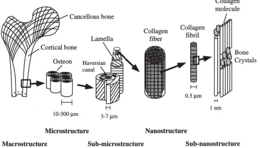
Figure 2.1 : Hierarchical structural organisation of human bone (Rho et al. 1998). Human bone matrix consists of approximately 60% of inorganic and 30% of organic components and 10% of water phases on a weight basis. Inorganic part is composed of calcium phosphate which mostly referred as hydroxyapatite (HA) (Ca10 (PO4)6(OH)2). Additionally, there are many trace elements such as copper, iodine, zinc, selenium, fluoride, manganese, which have positive effect on bone health (Zofkova, Nemcikova, & Matucha 2013). Also, the organic part is consists mainly of
6
collagen-I (90 wt%) in addition to other collagen types (III and VI) and various non-collagenous proteins. Bone tissue is formed its hierarchical structure from collagen fibrils (nanoscale) to lamellae (microscale) as shown in the Figure 2.1 (Keaveny, Morgan, & Yeh 2004).
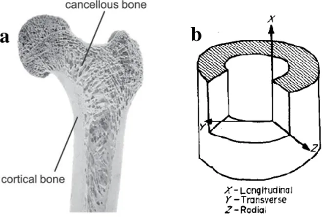
Figure 2.2 : a. Structure of bone at macro scale, b. Coordinate system for cortical bone specimen.
At macro scale, there are two types of bone; trabecular (cancellous, spongy) and cortical which are distinguished by their density and porosity. While lamellar and Haversian are tightly packed in cortical bone, cancellous bone has highly porous structure (Figure 2.2a) (Rho et al. 1998).
Mechanical properties of human femoral cortical bone was shown in the Table 2.1. Since bone has anisotropic character which means property of being directionally dependent (Figure 2.2b), tension, compression and elastic modulus values are different for longitudinal and transverse lines.
Table 2.1 : Anisotropic and Asymmetrical Ultimate Stresses and Elastic Properties of Human Femoral Cortical Bone (Reilly & Burstein 1975).
Longitudinal (MPa) Transverse (MPa)
Tension 135±15.60 53±10.70
Compression 205±17.30 131±20.70
Elastic Modulus 17900± 3900 10100±2400
Shear Stress (MPa) 65±4.00
a
b
7 2.1.2. Bone remodelling
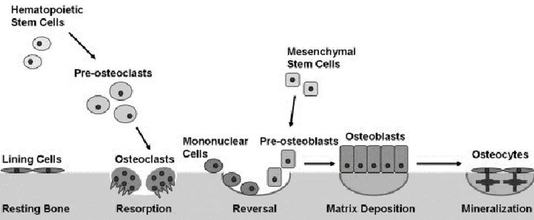
Bone is an active and dynamic tissue which has a high regenerative capacity and bone is remodelling continuously throughout life. There are three main types of cells which are responsible for this self-repairing process: osteoblasts, osteocytes, and osteoclasts (Florencio-Silva, Sasso, Sasso-Cerri, Simoes, & Cerri 2015; Kearns & Kallmes 2008) (Figure 2.3).
Osteoblasts (OBs):
OBs arise from mesenchymal cells which then differentiate into osteoprogenitor cells. These cells have a central nucleus and they produce organic bone matrix and help mineralisation to form new bone called “osteoid”. Moreover, they secrete factors that activate osteoclasts. OBs found on the surface of the new bone.
Osteocytes:
Osteocytes are mature bone cells and derived from osteoblasts. Approximately 90% of mature skeleton cells are osteocytes which entrapped in matrix and responsible from bone formation. Furthermore, regulation of calcium phosphorus concentration is balanced by osteocytes.
Figure 2.3 : Bone remodelling process (Kapinas & Delany 2011).
Osteoclasts (OCs):
OCs are large, poly-nucleated cells and arise from the monocyte/macrophage lineage. They are located on bone surfaces of the old, injured bone. Bone is resorbed
8
by osteoclast in bone remodelling. Additionally, they are exocrine cells that secrete enzymes, resorb extracellular matrix (ECM) proteins and dissolve bone minerals. At the end of the resorption, OCs undergo apoptosis which is programmed cell death.
2.2. Bone Tissue Engineering
Many different bone diseases such as bone infections, fractures and osteoporosis are more frequently seen due to the rise in the average age of population or traumatic reasons (Bose et al. 2012; Rauh et al. 2011). Since bone cannot manage to heal itself when a defect exceeds the critical size, autographs or allographs are used for bone reconstruction in order to improve bone healing (Brydone et al. 2010; Lichte et al. 2011). Although four million bone grafting are performed in the world annually, autographs and allographs have significant limitations and risks such as donor site morbidity, high infection risk and immune response (Brydone et al. 2010; Inzana et al. 2014).
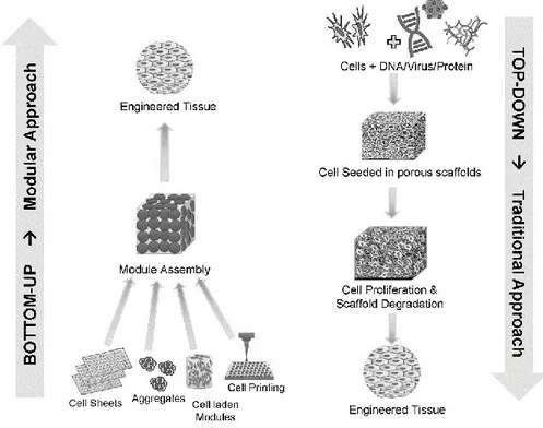
Figure 2.4 : Bottom-up and top-down approaches of tissue engineering (Tiruvannamalai-Annamalai, Armant, & Matthew 2014).
Tissue engineering (TE) offers various strategies with biocompatible and well-designed 3D bone scaffolds to lead tissue formation (Subia 2010). TE avoids
9
immunological responses and viral infections by using autologous cells (Stock & Vacanti 2001). There are mainly two approaches in tissue engineering; bottom-up and top-down. While in the first approach assembles the modules to reach the engineered tissue, second approach uses scaffolds for the same purpose (Figure 2.4). Top-down tissue engineering utilizes three main tools to restore, maintain, or improve function of tissue or whole organ. These tools are cells, scaffolds and stimulus (bioactive agents or mechanical stimuli) (Subia 2010).
Figure 2.5 : Concepts of tissue engineering (Stock & Vacanti 2001). l
As a basic concept of tissue engineering, cells are harvested from related organ (or stem cells can be collected from various stem cell sources). Then, desired cell line is isolated and cultured to increase cell number in vitro. Meanwhile, scaffold which should provide convenient biological and mechanical profile with natural tissue, is manufactured in 3D. Following that, cells seeded on scaffolds are cultured in a bioreactor to proliferate inside the pores of scaffolds and improve mechanical property. Afterwards, created tissue is implanted to damaged side of human body. For deep understanding, in the following section, potential scaffold materials, zinc as a dopant of scaffolds, conventional and additive manufacturing based scaffold production techniques and stem cells will be presented and personalized tissue engineering will be discussed at the end of the section.
10 2.1.1. Scaffold materials
Scaffolds are not used to replace the bone tissue permanently, they leads to simulate bone growth and remodelling. Design criteria for an ideal bone scaffold were summarized by Li et al. as shown in the Table 2.2. These three-dimensional platforms should not secrete any toxic product during degradation process during bone regeneration. Also, they should be biocompatible, osteoconductive (promote cell adhesion, proliferation and form ECM) and osteoinductive (induce new bone formation) which are essential properties for scaffold materials (Bose et al. 2012). Furthermore, a well-designed scaffold should have a perfect match with defect side along with having similar mechanical properties with host bone. In addition, manufactured scaffold should be sterilisable with any technique for clinical usage (Lichte et al. 2011).
Table 2.2 : Scaffold design criteria for bone tissue engineering (BTE) (Y. Liu, Lim, & Teoh 2013).
Criteria Function
Biocompatibility Ability to perform its function in the host tissue without eliciting any immune response
Biodegradability Tunable rate of degradation to match growth of new bone tissue as scaffold gets placed by new bone
Mechanical Properties
Sufficient mechanical strength to provide temporary support to the defect region and withstand in vivo loading forces
Microarchitecture Interconnected scaffold structures to uniformly distribute stresses throughout scaffold
Osteoinductivity Osteoinductive properties to recruit and differentiate osteoprogenitors to defect region
Porosity Large surface area: volume and pore size to allow for tissue in-growth, neovascularisation, mass transport and osteogenesis
Surface properties Appropriate chemical and topological properties for influencing cellular adhesion, proliferation and differentiation.
As such in biomaterials, scaffold are categorized in four groups; metallic scaffolds, ceramic scaffolds, polymeric scaffolds and composite scaffolds.
11 2.1.1.1. Metallic scaffolds
Porous metallic scaffolds are mostly made of titanium (Ti) and stainless steel (SS) which are biocompatible and relatively inexpensive metals. However, since metals have high compression strength and elastic modulus, it could cause stress shielding which limits mechanical stimulation and osteoblastic differentiation during bone healing. Moreover, metals are not biodegradable and may release metal ions. Due to mentioned disadvantages of metals, they are used in limited cases such as spine surgery. At the same time, various surface modifications or coatings are applied to increase bioactivity (Bose et al. 2012; Lichte et al. 2011).
Recently, magnesium alloys are developed as a biodegradable and biocompatible metallic scaffolds. Liu at al. investigated the biodegradation and osteogenic properties of magnesium scaffolds in vivo and they reported that it is a promising material for orthopaedics (Y. J. Liu, Yang, Tan, Li, & Zhang 2014).
2.1.1.2. Ceramics
Ceramics are commonly used in BTE because of their agreeable biocompatibility and good implant-host tissue integration. At the same time, since the dry inorganic part of bone is composed of 90 wt% calcium phosphate, ceramics are promising candidates to be used as scaffold materials to perfectly mimic the natural bone (Bose et al. 2012; Lichte et al. 2011). There are three main parameters for ceramic based materials; being bioinert, bioactive and bioresorbable which all have some benefits and limitations as shown in the Table 2.3.
Table 2.3 : Advantages and limitations of bioinert, bioactive and bioresorbable ceramics (Ducheyne 1999).
Category Advantages Limitations
Bioinert Minimal biological response, High wear resistance
Limited mechanical properties in tension
Bioactive Enhanced bone tissue response, Bone bonding
Limited tensile strength and fracture toughness
Bioresorbable Material is replaced by normal
tissue, thereby excluding possible long term effects
Rate of strength reduction may be too rapid
12
As it can be clearly seen from the table, the most important disadvantage of ceramic scaffolds for clinical usage potential is their low mechanical strength. Although ceramics have high brittleness, they have low wear rate. Because of their tribological characteristics, ceramics are mostly used in articulating surfaces. Another disadvantage of ceramics is that they are soluble at biological conditions easily (Y. Liu et al. 2013).
Mostly preferred ceramic based materials for BTE are calcium phosphates (CaP), bioglass and calcium sulphates (Paul & Sharma 2007). Tricalcium phosphate (TCP) and HA are classified under the group of CaP and both are highly biocompatible. CaPs were used in orthopaedic and dentistry since 1980s (Giannoudis, Dinopoulos, & Tsiridis 2005). They are available in powder, injectable, and semi-solid form to be used as bone filler. In 1969, Hench was observed that bone can bond to certain glass composition which called as bioactive glasses (Hench 1999) which have been used in various applications such as bone regeneration and implant coating (Yan et al. 2006). Finally, calcium sulfate (CaSO4) is an inorganic compound which exists in three levels of hydration; anhydrous state (CaSO4, anhydrite), dihydrate (CaSO4(H2O)2, gypsum) and hemihydrate (CaSO4(H2O)2, plaster of Paris, bassanite).
Calcium sulfate hemihydrate is produced by heating of gypsum and removal of three quarters of its water (Coetzee 1980).
𝐶𝑎𝑆𝑂4 . 2𝐻2𝑂 𝐻𝑒𝑎𝑡
→ 𝐶𝑎𝑆𝑂4 . 1 2⁄ 𝐻2𝑂 + 3 2⁄ 𝐻2𝑂 (1)
Then, approximately above 200 °C, hemihydrate transform into anhydrite form; 𝐶𝑎𝑆𝑂4 . 1 2⁄ 𝐻2𝑂 𝐻𝑒𝑎𝑡 → 𝐶𝑎𝑆𝑂4+ 1 2⁄ 𝐻2𝑂 (2)
The first reported usage of Paris plaster as a bone filler in patients was in 1892 by Dreesmann (Peltier 1959). Since calcium sulfate (CaSO4) is a glut in the market and has a low cost, it has been widely used biomaterials in bone regeneration more than 100 years (Beuerlein & Mckee 2010). In addition to its availability, CaSO4 has various advantages such as bioresorbablity, biodegradability, good osteoconductivity and biocompatibility to be used as a bone grafting material (Asadi-Eydivand, Solati-Hashjin, Farzad, & Abu Osman 2016; Orsini et al. 2001; Pietrzak & Ronk 2000; Thomas et al. 2005; Wu et al. 2012). Moreover, it releases calcium ions which may
13
provide an advantage for osteoblast formation (Thomas et al. 2005). Calcium sulphate hemihydrate (CaSO4 . 0.5H2O) was studied by Sidqui et al. (Sidqui, Collin, Vitte, & Forest 1995) who reported that osteoblastic cells attach on calcium sulphate hemihydrate and osteoclasts resorb the material. Wu H. D. and his colleagues demonstrated that combination of amorphous calcium phosphate and calcium sulphate improves osteoconductivity of materials and degradation period of this composite matching with natural bone regeneration rate (Wu et al. 2012).
CaSO4 was one of the earliest material used in 3D printers because of the fast setting characteristic of it (Asadi-Eydivand et al. 2016). Although this inexpensive medical grade resorbable CS has a long history in orthopaedics, powder based 3Dprinting technique may bring innovation to its usage in tissue engineering field (al Ruhaimi 2001). In contrast to its various advantages, one of the major challenge in usage of CaSO4 as a scaffold material is its low mechanical resistance and high solubility as such in other ceramics.
2.1.1.3. Polymers
Polymers could be categorized as natural and synthetic. Most common natural polymers used in TE are collagen, chitosan, hyaluronic acid, and alginate. Although they are biocompatible, control on degradation rate is difficult for this group.
On the other hand, main advantage of synthetic polymers is controlled degradation rate. However, since their degradation products creates local acidic environment it could cause negative tissue responses. Poly-lactic acid, poly-glycolic acid, and poly (lactic-co-glycolic) acid are U. S. Food and Drug Administration (FDA) approved polymers. In spite of their various mechanical and biological characteristics, both natural and synthetic polymers have good processability (Bose et al. 2012).
2.1.1.4. Composites
Since, composites are combination of two or more materials, it is possible to combine advantages of two distinct materials. Bone tissue is consist of both organic and inorganic compound with completely distinct properties. Thus, polymer and ceramic combination as a bone scaffold could meet mechanical and psychological
14
requirements of host tissue (Bose et al. 2012). The most commonly researched polymer/ceramic composite is polyesters with CaPs (Lichte et al. 2011).
2.1.2. Simulated body fluid
Simulated body fluid (SBF) is a solution which have nearly the same ionic concentration and pH value with inorganic content of human blood plasma. When ceramic samples are soaked in SBF solutions, it is seen that their surfaces coated with calcium phosphate. SBF is used to mimic physiological body condition and biological mineralization (Bayraktar 1999). In the Table 2.4 ion concentrations of human plasma and Tas’s SBF formulation were compared.
Table 2.4 : Ion concentrations of human plasma and SBF formulation of Tas (Bayraktar 1999).
Ion Human Blood Plasma
(mM) Tas SBF (mM) Na+ 142.0 142.0 K+ 5.0 5.0 Mg2+ 1.5 1.5 Ca2+ 2.5 2.5 HPO42- 1.0 1.0 HCO3- 27.0 27.0 Cl- 103.0 125.0 SO42- 0.5 0.5 Buffering agent - Tris
Biomaterials are soaked in SBF to investigate the potential apatite formation in body. When apatite layer is formed on the surface, bone forming cell will proliferate on it and fibrous tissue proliferation which occurs around foreign material will not be observed (Hench 1999).
2.1.3. Zinc oxide
Human body contains average 2-3 grams of zinc (Zofkova et al. 2013). And also, 0.0126 to 0.0217 % of human bone is zinc and this amount is higher than average of other fat-free tissues (0.0030 %) (Ito 2002).
15
Figure 2.6 : Effect of a. IGF-I on cell proliferation pathway (MacDonald 2000), b. Zinc on IGF-I pathway (Yamaguchi 1998).
Zinc is one of the most important trace elements in human body and known to aid cell proliferation, differentiation, regulation of DNA synthesis, enzymatic functions and also has an positive effect on bone formation (Alhava et al. 1977; MacDonald 2000; Paul & Sharma 2007). Growth and differentiation pathways of cells are composed of complex cascades which various molecules such as hormones and transcription factors have special roles. And zinc is one of the essential elements which is involved in cascades of many signalling pathways in eukaryotes (Beyersmann & Haase 2001).
Figure 2.7 : Effects of zinc deficiency (MacDonald 2000).
Growth inhibition and decreased food intake are major symptoms of zinc deficiency (Figure 2.7). Growth is regulated by hormones such as growth hormone (GH) and
a
b
16
insulin-like growth factor-I (IGF-I) (Figure 2.6(a)), although hormonal changes are not fully lightened, it is know that they are affected by zinc deficiency shown in the Figure 2.6(b) (MacDonald 2000).
By the help of deep literature research, it would be clearly seen that many researches have combined the advantages of zinc and ceramic to mimic the natural bone better. Ito et al. observed growth rate of MC3T3-E1 cells on 0.6 to 1.26% zinc containing ZnTCP/HA ceramic and conclude that addition of ZnO significantly increased cell proliferation and alkaline phosphatase activity. On the other hand, zinc content higher than 1.26% caused toxicity on cells (Ito 2002). Kewamura et al. used 0, 0.063, 0.316 and 0.633 wt% ZnO included ZnTCP/HA and they report that bone formation increases 51% in 0.316 % ZnO group compared to control (Kawamura et al. 2000). Bandyopadhyay et al. studied on 0.25, 0.5 and 1 % ZnO addition to TCP. Although they observe the highest density in 1% added group, since some concerns about cytotoxicity of ZnO higher than 0.33%, they continued to their further experiments with a group of 0.25% (Bandyopadhyay 2006). Calcium sulfate hemihydrate scaffolds with zinc concentrations of 0.074, 1.97, 3.05 and 4.21 wt% were investigated in terms of cell viability and activity by Hesaraki et al. While the maximum alkaline phosphatase (ALP) activity was achieved in a content of 0.74 wt% Zn group, they reported that higher concentrations more than 1.97 wt% causes toxic behaviour on G929 cells (Hesaraki, Nemati, & Nazarian 2009)
2.1.4. Scaffold manufacturing techniques
2.1.4.1. Conventional techniques for scaffold fabrication
Solvent casting
Solvent casting method is based on dissolution of polymer in organic solvent, casting polymeric solution into the mould and providing sufficient time for evaporation of solvent. Following, polymeric layer which adhere to mould could be created. Also, it could be combined with particulate leaching (Subia 2010).
17 Gas foaming
In this techniques, polymer exposure to high pressure CO2 (800 psi) to create highly porous scaffold. Pore intensity could be increased by using higher amount of CO2 gas. In the same manner, adding porogens such as salt, sugar and wax into polymer increases porosity (Subia 2010).
Electrospinning
Electrospinning is used to create polymeric fibres from nano to macro scales. In this technology, electrical field is generated by high voltage between the nozzle and ground. Polymer is pumped by using a syringe in the electrical field and polymer jet is accumulated on a ground or on a rotating collector. Fine, special oriented fibres could be created by this versatile technique (Figure 2.8) (Greiner & Wendorff 2007).
Figure 2.8 : Electrospinning setup.
Particulate leaching (porogen, salt leaching)
In this method, porogens such as salt, sugar and wax mixed with a scaffold material. At the end of the solidification process of mixture porogens will act as pore holder. Particulate leaching is one of the best techniques to have a control on size and density of pores.
Freeze drying
In freeze drying technique, firstly, polymer is dissolved in a solvent. Then, the solution is frozen to remove the solvent which is performed using by lyophilisation
18
under high vacuum to create porous scaffolds. Pore sizes controlled by freezing rate (Subia 2010).
Self-assembly
In self-assembly, molecules are organized spontaneously. One of the most common self-assembly methods is amphiphilic peptide sequence. In this technique, hydrophobic and hydrophilic peptides interact with each other in aqueous solution by using non-covalent bonds and create fast recovering hydrogel. Much thinner fibres could be produced by using self-assembly than other techniques (Subia 2010).
Table 2.5 : Advantages and disadvantages of conventional scaffold manufacturing techniques (Serra 2014; Subia 2010).
Method Advantages Disadvantages
Solvent Casting
Simplicity Low cost
Retention of toxic solvent Shape limitations
Low interconnectivity
Gas Foaming
Organic solvent
High temperature are not required
Low pore and geometry control
Electrospinning
Structural features similar to extracellular matrix, high aspect ratio and surface area
Organic solvent are used Low pore and geometry
control
Particulate Leaching
Control over pore size and density
Inadequate pore
interconnectivity
Freeze drying No need to separate leaching
Small pore size Long process time
Self-assembly
Control over porosity and fibre diameter
Expensive material
Complex design
19 2.1.4.2. Additive manufacturing
Additive manufacturing (AM), has been introduced since late 1980s (Khoo 2015). Unlike conventional production techniques additive manufacturing builds up the final geometry layer by layer. It also called as (solid) free form fabrication (SFF, FFF) or rapid prototyping (RP) (Upcraft 2003).
AM techniques has various advantages in comparison with conventional scaffold production techniques such as; excellent control over geometry, controllable and interconnected porosity, production of variable designs at the same time, material variety, minimum waste, fast and automatized manufacturing.
AM processes could be categorized into three main groups as liquid, solid, and powder based in terms of material phase. Stereolithography, selective laser sintering, laminated object manufacturing, fused deposition modelling and 3D printing will be explained in this section.
Stereolithography
Stereolithography (SL, SLA) was developed by 3D Systems Inc in 1988 (Gibson 2015). This technique uses UV light to solidify the photo-sensible liquid polymer in specific locations of each layer till the 3D models created (Hutmacher, Sittinger, & Risbud 2004; Wong & Hernandez 2012). In addition, higher resolution
micro-AM Processes Liquid based Melting FDM Polymerization SL Polyjet Solid Based LOM Powder Based Melting SLS EBM LENS Binding 3DP Prometal
Figure 2.9: AM Categorization according to raw material phase (Wong & Hernandez 2012) .
20
stereolithography which has layer thickness at least 10 µm is also available (Wong & Hernandez 2012). Furthermore, the residual polymer can be reused.
Figure 2.10 : Working principle of stereolithography (Krar 2003).
Selective laser sintering (Direct metal sintering)
Selective Laser Sintering (SLS) was patented by DTM in 1986 (Gibson 2015). This is a powder based fabrication technology that uses CO2 laser to fuse layers of plastic, metal, ceramic and composite powders. The chamber is heated until the melting point of the material in specific locations. Moreover, residual powder can be reused (Hutmacher et al. 2004; Wong & Hernandez 2012).
Figure 2.11 : Working principle of selective laser sintering.
Laminated object manufacturing
Laminated Object Manufacturing (LOM) was patented by Helisys in 1986 (Gibson 2015). In this technique paper, plastic or polymer sheet form materials are sliced layer by layer with carbon dioxide laser and then layers are laminated by pressure or heat to form 3D model (Hutmacher et al. 2004; Krar 2003; Wong & Hernandez 2012). However, its major disadvantage is that residual sheets cannot be reused.
21
Figure 2.12 : Working Principle of Laminated Object Manufacturing (Upcraft 2003).
Fused deposition modelling
Fused Deposition Modelling (FDM) was patented by Scott Crump from Stratasys Company in 1989 (Gibson 2015). In this technology material filament are melted and deposited (Upcraft 2003). FDM is one of the most preferred AM technique because of its cost efficiency and high quality.
Figure 2.13 : Schematic representation of FDM (Upcraft 2003).
Three dimensional printing
Three Dimensional Printing (3DP) was patented by a group from MIT in 1989 (Gibson 2015). In this manufacturing technology, the liquid binder is dispersed onto powder material to bind it together (Upcraft 2003). One thin layer of powder material is dispersed on a platform, following that the binder is sprayed onto the laid powder layer in powder based 3DP technique. The binder binds the powders to form a single 2D layer, so a sliced 2D profile of a computer model is created. This process occurs
22
many times to fabricate a 3D structure layer by layer until the whole model is completed (Lichte et al. 2011).
Figure 2.14 : Schematic view of 3DP process (Upcraft 2003).
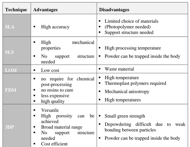
Each technique have both advantages and disadvantages as shown in the Table 2.6. Convenient method is chosen according to raw material and desired properties.
Table 2.6 : Comparison of 3D Scaffolding methods (Butscher 2013).
Technique Advantages Disadvantages
SLA High accuracy
Limited choice of materials (Photopolymer needed) Support structure needed
SLS
High mechanical
properties
No support structure needed
High processing temperature
Powder can be trapped inside the body
LOM Low cost Waste material
FDM
no require for chemical post-processing
no resins to cure less expensive high quality
High temperature
Thermoplast polymers required Mechanical anisotropy
High temperatures
3DP
Versatile
High porosity can be achieved
Broad material range No support structure
needed Cost efficient
Small green strength
Depowdering difficult due to weak bonding between particles
23
Figure 2.15 : Additive Manufacturing flow chart (Gibson 2015; Krar 2003).
Post Processes
At the end of the manufacturing, it is possible to apply some post processes to increase quality of fabricated scaffolds. Although it is time-consuming process, it enhance mechanical and physical quality of the materials. Post-printing manipulation, depowdering, coating, sintering and infiltration are some of those post process applications. Depowdering is removal of loose powder with brushing, blowing air, vacuuming, vibration, and wet depowdering (ultrasonicating, microwave-induced boiling and CO2 bubble generation in soda water). Coating is usually done with polymer-particle paste or slip casting to improve surface. Sintering and infiltration are applied to increase strength of structures, but scaffold structure is exposed to temperature that may causes shrinking in sintering. Dipping part,
CAD DESIGN
Data taken from CAD or Scanning system TRANSLATION
The 3D file must be translated into slice file (STL file format) that the AM system can read TRANSFER TO AM MACHINE AND STL MANUPULATION
Manupulation of the file for the correct size, position and orientation for building MACHINE SETUP
If the AM machine is not automated for parameters, setting such as layer thickness, delay time would be changed
BUILD
AM techniques builds physical models layer by layer REMOVAL
At the end of the production parts must be removed conveniently POST PROCESSING
Parts may require additional process to be cleaned of from support material or strengthed mechanically
APPLICATION
Parts are ready to be used, they should be sterilized with a convenient method such as autoclave or ethlene oxide according to material properties
24
aerosolizing infiltrant and spraying the part are infiltration techniques to get high density structures without the large shrinkage (Utela et al. 2008).
2.1.5. 3D cell and organ printing
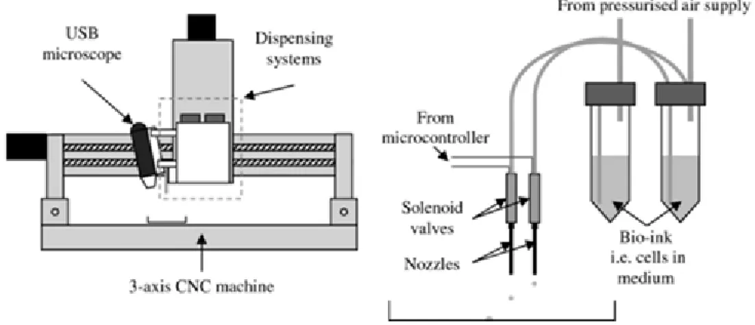
3D printing applications would be categorized into two groups in TE. First one is indirect printing which 3D printed scaffolds are produced by additive manufacturing technique. Following that cells are inoculated on scaffolds by using conventional TE applications. This technique covers top-down tissue engineering. Contrary to this, the second technique, bottom-up tissue engineering application, is direct cell printing which provide delivery of scaffold material, living cells, and stimuluses all together (Sun, Darling, Starly, & Nam 2004).
Figure 2.16 : 3D cell printing set-up (Faulkner-Jones et al. 2013).
Organ and tissue printing become popular in 2000s (Xu 2014). This technique enables to place cells more quickly and accurately. 3D cell printer can be designed with multi-nozzles which will distribute different cell types (Figure 2.16). In this way, it is a promising technique to design vessel network which is the main drawback of TE (Varghese et al. 2005). Cells are suspended in bio-ink solution which includes medium, polymer solution such as collagen and growth factors. Although there are commercial bio-printers on the market this system could be modified from ink-jet printers by displaying paper-feed mechanism and adding step motor control for movement in third axis (z-axis).
While basic models are created easily for cell and organ printing, since living tissues are composed of multiple cell types and vascular network in complex design, for 3D
25
tissue and organ printing, a model of detailed anatomy and morphology which called as bio-blueprint is required (Xu 2014). During printing process cells are deposited to right places in accord with this description. Bio-blueprint model includes; description of inner and outer architecture of an organ heterogenic tissue based and individual tissue boundaries, description of vascular network of the organ and a database about geometry, heterogeneity and vascularity (Sun et al. 2004).
2.1.6. Personalized bone substitutes
With emerge of SFF techniques, a new field have branched from TE that of computer-aided tissue engineering (CATE). This field contains design by using CAD, and manufacturing by using SFF. CATE highly interdisciplinary area which combines information technology, material science, mechanical engineering and TE. CATE mainly have three applications (Sun et al. 2004);
1. Computer-aided tissue modelling
2. Computer-aided scaffold design and manufacturing 3. Computer-aided tissue informatics
Computer aided tissue models could be captured by using CT (computed tomography), MRI (magnetic resonance imaging) and optical microscopy and re-constructed. Although captured 3D data can be directly altered to STL (stereolithography) format which is required for additive manufacturing and printed with AM system, due to many advantages such as modification flexibility model are converted into a CAD-based solid model.
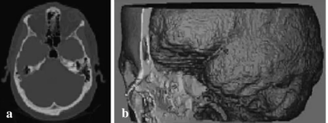
Figure 2.17 : a. 2D CT image, b. CT-derived 3D model of skull and brain (Sun et al. 2004).
a
b
26
CT and µ-CT(micro-CT) which used to show internal structure of sample, creates X-ray radiation and images the sample according to different absorption rates of different regions on it. Since µCT has high resolution, it is capable of showing internal structures of tissues. As a principle of CT, it created 2D (two-dimensional) images to create 3D representation. MRI can image soft tissues in addition to hard tissue. The output is 3D model created from 2D slices (Figure 2.17). Although MRI has capability to visualize various tissues, its resolution is lower than CT and optical microscopy (Xu 2014).
Figure 2.18 : Production of patient-specific bone grafts. a. CT scan data of patient, b. RP system software is captured to generate 3D model, c. Remodelling of defect
side, d. Scaffold building, e. Scaffold design, f. defect side from sliced data, g. defect-scaffold match (Hutmacher et al. 2004).
The main aim in personalized bone substitutes is to produce defect-matching scaffolds. There are certain essential steps for production of patient specific implants or grafts (Figure 2.18). Firstly, 3D model of defect side should be captured by CT scan and imported to the program. If the defect side has a healthy mirror image on body (such as deficient right hand, health left hand), CT data of the health area is captured to be used as a scaffold model. Otherwise, this model should be created by CAD (Computer Aided Design) software such as Solidworks or Inventor. After
27
designing the inner architecture (flat or porous) and outer shape of the scaffold or implant, model is produced slice by slice by convenient AM technique according to material type. 3D printing is one of the best techniques particularly for custom designs on artificial bone applications because of the high controllability, design independency, fast producibility, reproducibility, no waste material, variety of material. Finally, patient specific model is sterilized and ready to be used in vitro or in vivo.
As a top-down TE approach, cells which are isolated from individual’s body is inoculated on manufactured scaffold for personalized bone scaffold applications after sterilization process. Osteoblastic cell or stem cells could be used in this process. Stem cells are unspecialized cells and capable continuous of self-renewal. They can give rise to specialized cell types (Sharma 2014). Mesenchymal stem cells (MSCs) are found in multiple tissues including bone marrow. Although 0.001%-0.01% of the entire bone morrow cells, MSCs can be expanded by using cell culture techniques. They can differentiate into osteoblasts. The main advantage of usage of MSCs in TE is that they can be used without immune rejection. Following inoculation of BMSC (bone marrow stem cell) to the scaffold, they are subjected to osteogenic differentiation by using various environmental and biological factors (Eslaminejad & Faghihi 2011).
29 3. MATERIAL AND METHOD
3.1. Manufacturing
3.1.1. Powder preparation
Commercial powder of 3D printer (Projet 160, 3DS USA) purchased from 3D Systems. Asadi-Eydivand et al. indicates that commercial powder (calcium sulfate hemihydrate, CSHH) of 3DS printers has a particle size distribution 10%, 50% and 90% of powder below 0.64, 27.36 and 68.83 µm, respectively (Asadi-Eydivand et al. 2016).
High purity zinc oxide (ZnO) was purchased from Merck (USA). Powder was doped with 0.1 wt%, 0.3 wt% and 0.5 wt% ZnO.
0 wt %, 0.1 wt %, 0.3 wt % and 0.5 wt % zinc doped powder was prepared by following reference study (Fielding, Bandyopadhyay, & Bose 2012).
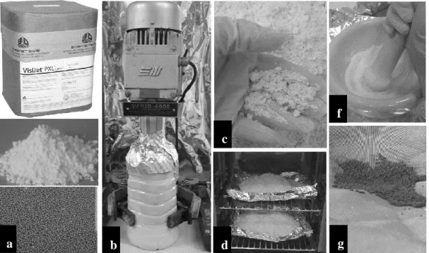
Figure 3.1 : Powder preparation process a. CSHH powder, zinc oxide and zirconia milling media (respectively), b. Homogenisation process, c. humid mixture after ventilation, d. powder mixture in drying oven, f. Pestling process, g. Sifting and removing the milling media.
f
a b
c
30
ZnO in varying concentrations (0 %, 0.1 %, 0.3 % and 0.5 %), 3 kg of powder, 1 kg of 1 mm zirconia milling media and 2 litre ethanol added for each group and mixed with mixer (Yokes Mixer Vario 6000, Turkey) for 2 hours at 250 rpm.
At the end of the 2 hours blending, mixture was spread on a tray and ventilated to evaporate ethanol without ossification at room temperature for 24 hour. Following that, the mixture transferred on aluminium foil and placed in a 60 ºC of drying oven for 48 hours. Then, the agglomerated mixture was pestle roughly and the mixture was sifted to remove the milling media with sieve. Following that, mixture was dried for another 24 hours in drying oven.
3.1.2. Scaffold design and fabrication
CAD files of test samples were created by CAD software (Autodesk Inventor Professional 2014, USA) as a requirement of 3DP process. Cylindrical block scaffolds Ø 10 mm, 5 mm height and Ø 10mm, 10 mm height was designed for cell culture and compression tests respectively. All experiments were performed by using non porous block samples to test solubility, mechanical and biological property of the material. But yet, 500 µm, 750 µm and 1000 µm porous scaffolds were designed to check the solubility and to optimize the pore size and intensity as a preliminary research for future study (Figure 3.2).
Figure 3.2 : CAD models of 3D printed porous scaffolds.
Following the design process, they were exported as .stl (surface tessellation language, stereolithography) which is the file format allowing to define 3D models using just triangle meshes. STL format can be directly imported to AM devices. Data were imported to 3D printing software (3DP Projet X60, Ver. 1.01, USA) where models were sliced by a slicing algorithms itself.
31
Figure 3.3 : Sample production process a. emptying and cleansing printer feeding chamber, b. printing parts with loaded powder, c. collecting samples from building area, d. depowdering loose powders by using air blowing e. pre-baked samples, f. sintered samples, g. sintered and non-sintered samples, h. all manufactured groups.
After preparation of powder mixture for each groups (4 group), powders was loaded to 3D printer starting from control and continued by increasing concentrations. The main drawback was to cleanse 3D printer at the end of the each printing process not to lose control on zinc concentrations of groups. 2D sliced layers were printed layer