2020, 4(2)
2602-2052 DOI: 10.30521/jes.690997 Research Article
The electromagnetic modeling and the co-simulation of a direct drive axial
flux permanent magnet synchronous generator
Mustafa Akin
Karamanoglu Mehmetbey University, Graduate School of Natural and Applied Sciences, Department of Electrical and Electronic Engineering, Karaman, Turkey, [email protected]
Selami Balci
Karamanoglu Mehmetbey University, Faculty of Engineering, Department of Electrical and Electronic Engineering, Karaman, Turkey, [email protected]
Submitted: 18.02.2020 Accepted: 17.03.2020 Published: 30.06.2020
Abstract: Direct drive (gearless) axial flux permanent magnet synchronous generators (AFPMSG) are
designed as multi-pole for use in vertical axis wind turbines. In particular, there are multi-pole core/coreless stator structures with axial flux for use in vertical axis wind turbines (WT) that can be designed in a compact structure at low wind speeds. In this study, the parametric simulation studies have been carried out according to rotor mechanical speeds with certain linear steps depending on different wind speed scenarios for an AFPMSG designed with 16-pole and cored stator for 5 kVA rated power with the finite element analysis (FEA) software. According to the analysis results obtained, the performance of the generator is reported and current, voltage, power losses and the flux distribution are investigated. In addition, the DC link voltage at the output of the DC-DC boost converter circuit due to wind speed changes is adaptively controlled for AFPMSG, which is co-simulated with the power electronics interface used at the generator output. Thus, both power electronics circuit performance and generator side have been simulated simultaneously with electromagnetic modeling. Therefore, the performance of the designed AFPMSG, which is modeled in three dimensions (3D) before the prototype stage, can be determined under more realistic conditions.
Keywords: Direct drive AFPMSG, Parametric FEA, Power electronics interface, Wind generator, Wind
speed
Cite this paper as:
Akin, M., & Balci S., The electromagnetic modeling and co-simulation of a direct drive axial flux permanent magnet synchronous generator. Journal of Energy Systems 2020, 4(2), 32-47, DOI: 10.30521/jes.690997
© 2020 Published by peer-reviewed open access scientific journal, JES at DergiPark (https://dergipark.org.tr/en/pub/jes)
Nomenclature
AFPMSG Axial Flux Permanent Magnet Synchronous Generator FEA Finite Element Analysis
PM Permanent Magnet WT Wind Turbine
MPPT Maximum Power Point Tracking EMF Electromotive Force
1. INTRODUCTION
Wind energy as a renewable environmentally friendly energy source has gained popularity in a windmill application in the old ages. It has shown a remarkable usage increase for electricity generation since the new millennium. In this context, much more wind turbine production systems are being installed all over the world to provide social, environmental and economic benefits [1]. There are various generator types used in wind turbine systems: induction (asynchronous) generators, DC excited synchronous generators and Permanent Magnet Synchronous Generators (PMSG). These are three types of the most commonly used generators in wind turbine systems. PMSGs are generally preferred in small and medium power wind turbine systems and especially in small power wind turbine systems. They are used in both – grid-connected energy production systems and island-mode energy production systems [1-2]. PMSGs have some advantages over asynchronous or excited synchronous generators. They are more efficient, stable and reliable and come first in the selection of generator. The use of scarce elements in the manufacturing of permanent magnets (PM) has accelerated the production of permanent generators. This has increased the popularity of PMSG in the wind energy systems. PMSGs became important since the 1980s after NdFeB magnets were invented [3-4]. There are two different types of PMSG discussed in the literature such as Axial Flux and Radial Flux PMSGs. If the magnetic flux passes through the coils that form a radial flux on the same axis, this type of generator is called a radial flux generator. On the contrary, if the magnetic flux passes perpendicular to the radial axis, it is defined as an axial flux generator [5].
In comparison to excited generators, PMSG also has a number of economic and technical advantages, as they became widely spread for direct drive WTs. The advantages of PMSG can be summarized as more efficient, no power supply is needed for magnetic field excitation, improved thermal properties due PM use for excitation instead of windings, more reliable due to the absence of mechanical components such as brushes and rings, lighter and therefore having higher power density (kVA/kg). However, PMSGs have some disadvantages that can be summarized as follows: limited technology for application in the higher power range (MW), high PM material cost, production difficulties, low material reliability in harsh atmospheric conditions, high temperature PM demagnetization [6-8]. However, it could be mentioned that recently PMSGs have been applied more widely for large-scale wind turbine systems, with improved performance and reduced cost of PM materials [9].
The technology of the axial flux PM generators was defined towards the 90's, and thus the basic axial core structure was determined for the direct drive wind turbines [10, 11]. On the other hand, PMGs can be produced with lower construction, operating costs, is less noisy and adapts faster to wind speed changes and load variation. In addition, the gearless system can operate under low wind speeds because the rotor is designed with a greater number of poles. Thanks to the disc shape (for axial flux) of AFPMSG machines, it is commonly easier to design and produce machines with multiple poles [12]. In addition, five-phase and nine-phase samples as a multi-phase designs are discussed in the literature. Thus, as the number of phases increases, the rectifier output voltage at the generator output becomes smoother and the filter requirement decreases [9, 12]. The rotor speed is regulated by the speed controller using wind speed as a reference value in the control system proposed in [13] together with the power electronics circuit interface eliminating output voltage fluctuations of PMSGs. Thus, the wind turbine can be controlled by a control strategy similar to monitoring the maximum power point tracking (MPPT). In another study, since the frequency and amplitude of the three-phase voltages produced by the gearless direct drive PMSG definitely depend on the rotor speed, experimental tests and system behavior were determined under different wind speed values. A power electronics circuit was then designed to convert the AC voltage of the generator to DC, and it is proposed suitable for the output of the PMSG. Thus, stable voltage amplitude and frequency value were provided, and the battery unit was charged for efficient energy storage [14].
In the literature, besides prototype studies, there are also studies related to the establishment of solar energy systems and hybrid systems. Its importance is emphasized in hybrid systems created with small
wind turbines, especially in rural areas or where it is difficult to reach power lines [15]. Therefore, it is important to develop high efficiency alternators for small powerful wind turbines, and finite element analysis (FEA) software stands out in the design of permanent magnet alternators. One of the software using FEA is Maxwell 2D/3D of ANSYS. Thus, the electromagnetic analysis can be performed during the development of permanent magnet alternators [15-23]. Before the prototype stage, the simulation studies with the electromagnetic analysis Maxwell software revealed that more realistic modeling was provided and the validity of the data obtained. In addition, the co-simulation facility provides both a power electronics circuit and a suitable opportunity for the performance testing together with electromagnetic modeling [17-19].
In this study, the analysis results obtained with the FEA parametric solver depending on different wind speed scenarios for an AFPMSG designed with Ansys-Electronics Maxwell 3D software for a 16-pole and 5 kVA rated power are reported comparatively. For the designed AFPMSG, which is performed the co-simulation studies with the power electronic circuit used of the generator output; the DC link voltage due to wind speed changes is adaptively controlled with the DC-DC boost converter circuit. Thus, both power electronics circuit performance and generator side are simulated with the electromagnetic modeling.
2. ELECTROMAGNETIC MODELING WITH FEA SOFTWARE
The finite element analysis is the application of the finite element method with a software for the solution of a particular physical problem. For example, if a two-dimensional (2D) or three-dimensional (3D) modeling is to be solved, FEA can be used as a parametric solver for a mathematical solution. The problem area can be divided into finite elements as a planar element and can be solved as a differential equation. In order to be able to design and simulate electrical machines with FEA software, the stages followed in electromagnetic modeling are systematically followed as given in Figure 1. Most commercial FEA software provides built-in analytics tools or modeling templates, where 2D/3D geometry and the analysis reports can be obtained with the fundamental generator parameters. However, these models are limited to specific generator types, and an extra study with the other computer-aided drawing software is required to continue detailed FEA modeling and simulation [24].
In these stages, after determining the solver type, model geometry is drawn as 2D/3D for the electromagnetic modeling, boundary and excitation conditions are defined. In the analysis settings stage, simulation conditions are determined for solution setup. According to the data obtained as a result of the analysis, reports such as numerical values, 2D/3D graphics and electromagnetic field drawings are obtained [17-19].
Figure 1. Electromagnetic modeling flow chart with FEA software [17-19].
It should be remembered that achieving the most suitable design for an electric machine is a difficult issue, mainly due to a large number of variables, constraints, non-linearity, and many criteria for improving performance [24]. In this case, the nonlinear behavior of the system cannot be precisely modeled with classical mathematical methods. Maxwell's equations are the fundamental electromagnetic areas. The electromagnetic vector potential is a potential A function that can easily create boundary conditions, and it is commonly used to calculate the 2D electromagnetic field, since it can facilitate the achievement of flux and magnetic field density. The differential version of the Maxwell equation in the transient field can be expressed by Eq.1 [25-27].
C S v H t A J A v − + − =
(1)where A is the electromagnetic vector potential, JS is the current density, HC is the coercive force of PM and v is the rotation object speed. According to the finite element method, the continuous electromagnetic field is converted into discrete systems with network division. Temporary solver can calculate back EMF, electromagnetic flux and torque. The leakage coefficient σ is the ratio of PMs to the total magnetic flux Φm and the air gap main magnetic flux Φg entering the armature in given Eq. 2
[25]. g m =
(2)To reduce the sizing of PMs, electromagnetic flux leakage should be minimized because the volume of PMs is proportional to the leakage coefficient [25]. Rated torque of PMSG equals average mechanical torque. By neglecting viscous resistance, maximum electromagnetic torque (Te(max)) can be achieved as
seen in Eq. 3 [28]. m t m e
T
J
T
(max)=
(max)+
(3)Also, Tm(max) is the maximum rotor torque, Jt is the total inertia torque and βm is the maximum slowdown
during the braking. The generator terminal voltage Vs voltage vector given in Eq. 4 is the back EMF in
Eq. 5, Is current vector, R winding resistance, ωe electrical angular velocity, ψf PM flux linkage and Ls
inductance [28].
(
) (
2)
2 S S e S S SE
I
R
L
I
V
=
−
+
(4) f e SE
=
(5)For the star-connected generators, the voltage vector is limited to DC voltage level. Thus, it can be seen that the back EMF is limited. In addition, phase-to-phase back EMF should not exceed the DC voltage level, otherwise the rectifier circuit becomes out-of-control. According to the general electrical circuit analysis, the back EMF at maximum speed is selected by the following. Also, ke is a safety factor, and
voltage drops due to inductance and resistance are relatively smaller in PMSGs placed on the surface, so ke, 1.0 or a little less can be taken. The rated torque value, PM flux linkage and the winding current
can be determined according to expressions as Eq. 6 [28]:
S f e p I T
2 3 = (6)where Te is the electromagnetic torque of the generator and p is the number of poles. The axial part has
little effect on the calculation of the PM flux linkage due to the anisotropic nature of the core material. Thus, the following expression (in Eq. 7) can be written for the voltages induced in the generator windings [27].
( )
t Nf
Vph= 2
ph phcos
(7)Finally, Vph, f, Φph and Nph are output phase voltage of the PMSG, operating frequency, magnetic flux
per pole and number of coils turns in series per phase, respectively.
3. MODELING AND SIMULATION OF THE DESIGNED AFPMSG
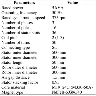
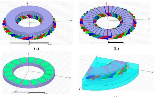
Technical specifications of 16-poles AFPMSG designed in three dimensions are given in Table 1. In this table, the mechanical parameters of the stator and rotor sections are used. The image of the modeled generator in the Ansys-Rmxprt software in 2D modeling is shown in Figure 2(a). Stator winding structure is defined as star-connected and shortened-step full wound winding as given in Figure 2(c) and (d). NdFeB-XG96 / 40 type magnets as the material of the poles and its placement in the rotor part as 16 poles are shown in Figure 2(b). Here, magnet sizes are a completely unique design for AFPMSG and are sized for 5kVA power. NdFeB-XG96 / 40 magnet Maxwell software is available in the Rmxprt library and has a flux density value of about 1.23 T.
Table 1. Technical features of the designed generator
Parameters Value
Rated power 5 kVA Operating frequency 50 Hz Rated synchronous speed 375 rpm Number of phases 3 Number of poles 16 Number of stator slots 36 Coil pitch 2 (1-3) Number of turns 50 Connecting type Star Stator outer diameter 500 mm Stator inner diameter 300 mm Stator length 50 mm Rotor outer diameter 500 mm Rotor inner diameter 300 mm Air gap distance 1.5 mm Stator stacking factor 0.95
Core material M19_24G (M330-50A) Magnet type NdFeB-XG96/40
(a) (b)
(c) (d)
Figure 2. Designed AFPMSG image, a) stator part with 36 slots, b) rotor part with 16 poles, c) stator winding with the shortened pitch, d) stator winding distribution with slot numbers
The full view of designed AFPMSG in FEA software is given in Figure 3(a). The stator part and the placement of the three-phase windings are given in Figure 3(b), and the 16-pole rotor structure image in Figure 3(c). Thus, the mechanical structure of the designed generator can be clearly seen. The air gap distance between the rotor and the stator is 1.5 mm and the stator grooves are modeled without slope. Symmetrical modeling can be performed with FEA software as shown in Figure 3(d) in order to shorten the simulation and meshing time on the 1/4 ratio of the generator. Thus, long-term simulation and unnecessary memory usage can be prevented [19].
(a) (b)
(c) (d)
Figure 3. Designed AFPMSG in FEA software, a) full image, b) only stator part image with three-phase shortened pitch windings, c) only rotor part image with 16-poles, d) 1/4 model symmetry of AFPMSG
As the core material of the stator and rotor parts, the non-oriented M19 core material with B-H slope is used in the graph given in Figure 4. The saturation flux value of this core material is given in the manufacturer's data sheets as specific core loss of 3.33 W/kg for the mains frequency of approximately 1.7 T and 50 Hz [29]. This core material is available in the FEA software library and is commercially available core material.
Figure 4. Non-oriented core material B-H curve 3.1. Parametric Simulation Studies of AFPMSG
In this study, parametric simulation studies are performed for the modeled AFPMSG according to different wind speed scenarios. Since the designed generator is gearless, it is expected that it will generate voltage at different pole speeds and amplitude and frequency values in 16 poles structure. Therefore, the voltage produced by AC-DC converter at the three-phase generator output with different amplitude and frequency values is converted to the correct voltage. Thus, it can produce even at low wind speeds, and a power amplitude and frequency value of AC power can be provided with the power electronic circuit interface, and production can be made for a certain power in gearless direct driven wind generators in any case. In order to run in parametric simulation, it is defined with a linear step (with 25 rpm) increase from 125 rpm to 325 rpm with FEA solver from mechanical setup menu. Thus, the rotor position graph for 500 ms simulation time is displayed as given in Figure 5 and a rotation is completed as a rotor position at 500 ms even at low speed.
Figure 5. Generator rotor positions due to mechanical speed transient response in different wind speeds
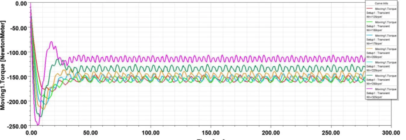
Based on the parametric simulation studies, the moving torque curves of the generator for the rotor speeds formed at different values according to different wind speed scenarios are obtained as in Figure 6. As the generator output electrical load is at a constant value, a decrease in moving torque has occurred at rotor speeds from 250 rpm to 325 rpm. Thus, torque-speed behavior can be determined for the generator designed with FEA prior to the prototype, in fact, it is recommended to change the generator load for constant torque behavior since constant rotor speed is not expected.
Figure 6. Generator torque transient response in different wind speeds
However, the changes in the three-phase voltage amplitude and frequency values induced in the stator windings, as the rotor speed and torque values change, are given in Figure 7. Thus, depending on the parametric voltage graph, the current amplitudes drawn under constant load at the generator output are also at different values. Although this may seem like a complex graphic, it constitutes important data for determining the control strategy of the power electronics circuit.
Figure 7. Generator voltage transient response in different wind speeds
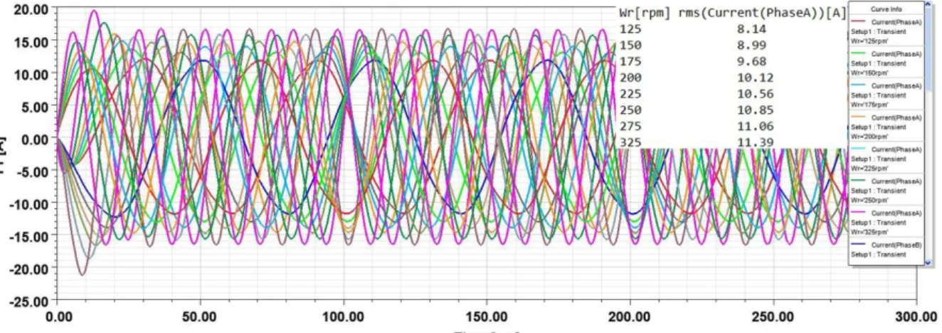
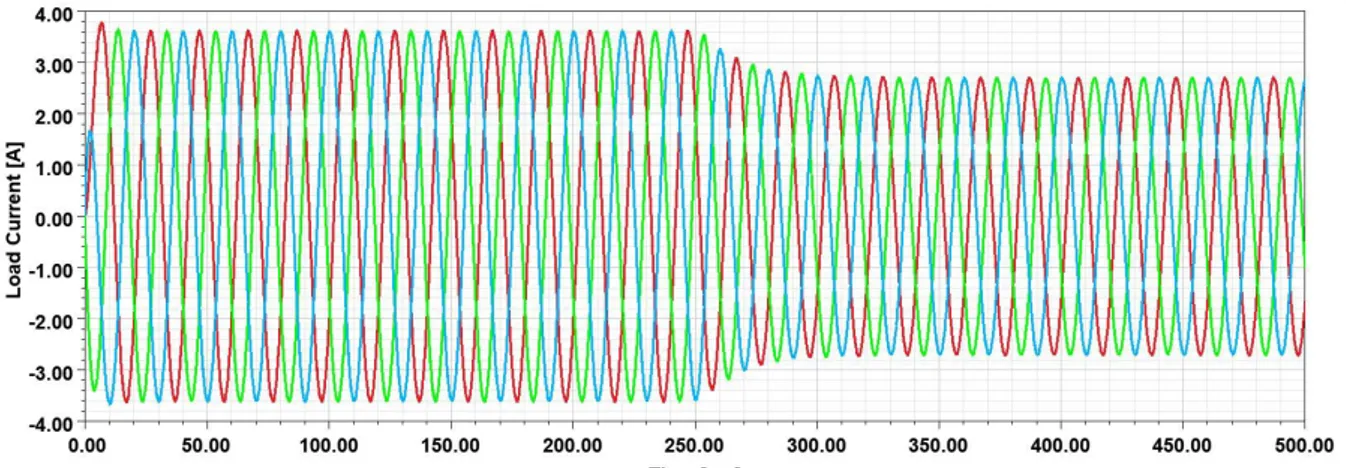
As can be seen from the load current graphs given in Figure 8, the electrical behavior of the generator is significantly affected due to different wind speed values, and thus the efficiency of the generator changes at any time.
Figure 8. Generator loadcurrent transient response in different wind speeds
The core and winding losses, which are among the most important determinants of generator performance, are also affected by different wind speed values. Since the rotor will move at lower speed than it should be at low wind speed values, both the generated voltage amplitude and frequency value are at smaller values, so the core losses are smaller than the high wind speeds as given in Figure 9.
Likewise, winding losses occurring in the stator part of the generator take different values as the load current values change as seen in Figure 10. Thus, the generator loss values for parametric wind speeds change and the efficiency is highly affected.
Figure 10. Generator winding loss transient response in different wind speeds
According to these parametric graphs, voltage and current graphs for only 250 rpm rotor speed value can be given in Figure 11 and Figure 12. Thus, it has been determined that it has the capacity to provide approximately 5 kVA apparent power value in accordance with generator specifications.
Figure 11. Generator voltage graph for 250 rpm mechanical speed
In this case, the generator core and winding losses occurred as in Figure 13 and Figure 14, respectively. Thus, the designed AFPMSG efficiency is approximately 88%, which is a good value for 250 rpm wind speed.
Figure 13. Generator core losses graph for 250 rpm mechanical speed
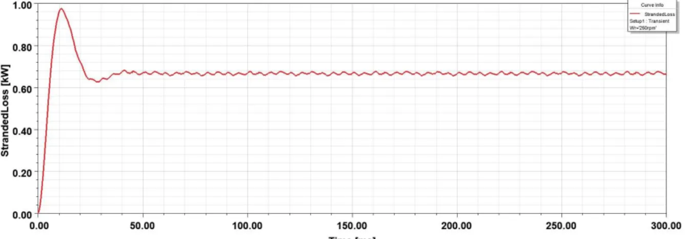
Figure 14. Generator winding losses graph for 250 rpm mechanical speed
Designed AFPMSG flux distribution was obtained as shown in Figure 15 for maximum 2 T value. The flux distribution in the stator/rotor base, slot teeth and PM poles can be examined, and if there is a saturation effect, the most suitable design can be achieved in a shorter time and with fewer costs by changing the mechanical parameters before the prototype design.
Figure 15. Flux distribution of AFPMSG 3.2. The Co-simulation of AFPMSG with Power Electronics Interface
The electromagnetic equivalent circuit of the generator designed with FEA software can be run together with the power electronics circuit software as co-simulation [30]. In this section, the step response of the power electronics interface at the generator output for the change in the rotor speed of the generator based on two different wind speed values is analyzed. The main parameters and technical features of this power electronics interface are given in Table 2. According to the results obtained from parametric simulation studies, in the case where 150 V and 200 V DC voltage is obtained at the rectifier output for two different rotor speed values of the generator, adaptive duty cycle control was performed to provide 400 V DC link voltage at the DC-DC boost converter output. Thus, the co-simulation circuit is given in Figure 16 for the power electronics circuits’ interface.
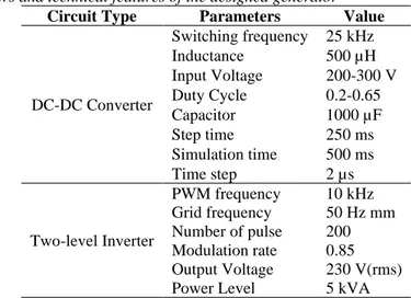
Table 2. Main parameters and technical features of the designed generator Circuit Type Parameters Value
DC-DC Converter Switching frequency 25 kHz Inductance 500 µH Input Voltage 200-300 V Duty Cycle 0.2-0.65 Capacitor 1000 µF Step time 250 ms Simulation time 500 ms Time step 2 µs Two-level Inverter PWM frequency 10 kHz Grid frequency 50 Hz mm Number of pulse 200 Modulation rate 0.85 Output Voltage 230 V(rms) Power Level 5 kVA
If the adaptive control is not performed, as shown in Figure 17, when the generator speed decreases in 250 ms, the DC bus voltage decreases from 400 V to 300 V.
Figure 17. Inverter input voltage step response due to generator speed change without adaptive duty control.
Thus, since the inverter output voltage is also decreasing in amplitude, it creates a negative situation for the load and the load current is also affected. In this condition, the inverter output voltage is given in Figure 18, and the current graph passing over the load is given in Figure 19.
Figure 19. The load current step response due to generator speed change without adaptive duty control.
In order to keep the stable DC link voltage (as 400 V) value dependent on wind speed constant at the input of the inverter, when the duty cycle value of the boost converter circuit is 0.33 at 200 V input voltage value, the converter input is adjusted to 0.50 to provide a voltage value of 400 V DC to the bus voltage as seen in Figure 20 according to the wind speed fluctuations. This control system continuously adjusts the duty cycle value according to the dependent changes. Thus, the voltage and load current amplitude values on the load constantly remain stable as given in Figure 21 and Figure 22, respectively.
Figure 20. Inverter input voltage step response due to generator speed change with adaptive duty control
Figure 22. The load current step response due to generator speed change with adaptive duty control.
Thus, under the changes in wind speed, the step response of the power electronics interface for two different rotor speed values provided a constant voltage on the load. This co-simulation circuit provides useful information to determine both power electronics circuit performance and generator electromagnetic performance.
4. CONCLUSION
In this study, a 5 kVA 16-poles direct drive AFPMSG design are realized with FEA software and parametric modeling and simulation studies are performed according to wind speed changes. Thus, the generator torque value did not show much variation in the rotor speed range between 125 rpm and 225 rpm, but when the rotor speed reached 325 rpm, it decreased to 125 Nm. In addition, the rms value of the generator voltage increased from 80 V to 115 V depending on the increase from low rotor speed to high speed. For the generator losses; the core loss occurred in the range of 15-30 W, and the winding losses are in the range of 400-750 W. Thus, the core and the winding losses also take different values due to the change in power and frequency value provided depending on wind speeds. According to the data obtained, when the change in rotor speed values is considered in terms of performance, it affects the voltage amplitudes, frequency values, torque values and loss values of the generator. In this context, three-phase AC voltages with the different frequency and amplitude values produced for each wind speed values for direct driven wind generators are first converted to DC voltage with the power electronic circuit interface. Then, the DC-DC boost converter circuit is used with adaptive duty control to keep the DC link voltage constant at 400 V DC. In addition, this interface circuit topology has a three-phase two-level inverter circuit to provide constant amplitude and frequency voltage on the load. Thus, AFPMSG performance is determined with the power electronics circuit software Twin Builder, which is run as co-simulation with FEA software, and 3D modeling is provided in more realistic conditions before prototype design.
REFERENCES
[1] Guo, Z. & Chang, L. FEM study on permanent magnet synchronous generators for small wind turbines, IEEE
Canadian Conference on Electrical and Computer Engineering, (CCECE/CCGEI), 1-4 May 2005, Saskatoon,
Canada, pp.641-644, DOI: 10.1109/CCECE.2005.1557012.
[2] Chang, L. & Wang, Q. Application of finite element method in design of a 50kW direct drive synchronous generator for variable speed wind turbines”, IEEE Canadian Conference on Electrical and Computer Engineering.
Conference Proceedings, (CCECE), 2002, Canada, pp.106-111, DOI: 10.1109/CCECE.2002.1015183.
[3] Kurt, E. & Gor, H. Electromagnetic design of a new axial flux generator, IEEE 6th Edition Electronics, Computers
[4] Kurt, E., Gor, H., & Doner, U. Electromagnetic design of a new axial and radial flux generator with the rotor back-irons, Int. Journal of Hydrogen Energy, 2016, 4(1), 7019-7026.
[5] Wallace, RR., Lipo, TA., Moran, LA, & Tapiai, JA. Design and construction of a permanent magnet axial flux synchronous generator. IEEE Electric Machines and Drives Conference, 1997, USA, pp. MA1/4.1-MA1/4.3, DOI: 10.1109/IEMDC.1997.604061
[6] Mellah, H. & Hemsas, K. Simulations analysis with comparative study of PMSG performances for small WT application by FEM, International Journal of Energy Engineering, 2013, 3(2), 55-64.
[7] Li, H. &Chen, Z. Overview of different wind generator systems and their comparisons, IET Renewable Power
Generation, 2008, 2 (2), 123-138.
[8] Mihai, AM., Benelghali, S., Simion, AI., R. Outbib, R., & Livadaru, L. Design and FEM Analysis of five-phase permanent magnet generators for gearless small-scale wind turbines, IEEE 20th International Conference on
Electrical Machines, 2012, pp.150-156, DOI: 10.1109/ICElMach.2012.6349856.
[9] Xue, YS., Han, L., Li, H., & Xie, LD. Optimal design and comparison of different PM synchronous generator systems for wind turbines, IEEE International Conference on Electrical Machines and Systems, 2008, Wuhan, China, pp.2448-2453.
[10] Ege, ES. The design of a transversal flux permanent magnet synchronous machine for direct driven wind turbines, (M.Sc.), Institute of Science and Technology, Istanbul Technical University, Istanbul, Turkey, 2009.
[11] Weh, H. Transverse-flux machines in drive and generator application, Proceeding of the IEEE Symposium on
Electric Power Engineering, 1995, Stockholm, Sweeden, pp. 75-80.
[12] Shokri, M., Behjat, V., & Rostami, N. Characterization of axial flux permanent magnet generator under various geometric parameters for improved performance, Gazi University Journal of Science (GU J. Sci.), 2015, 28 (2), 285-294.
[13] Han K. & Chen, GZ. A novel control strategy of wind turbine MPPT implementation for direct-drive PMSG wind generation imitation platform, IEEE 6th International Power Electronics and Motion Control Conference,
(IPEMC), 2009, Wuhan, China, pp.2255-2259, DOI: 10.1109/IPEMC.2009.5157778.
[14] Guler, N., Irmak, E., Gor, H., & Kurt, E., An inverter design for a new permanent magnet synchronous generator,
Int. Journal of Hydrogen Energy, 2017, 4(2), 17723 -17732.
[15] Sinha, S. & Chandel, SS. Prospects of solar photovoltaic – micro-wind-based hybrid power systems in western Himalayan state of Himachal Pradesh in India, Energy Conversion and Management, 2015, 105(15), 1340-1351. [16] Huner E. & Ataozden, Y. Electromagnetic design and analysis of an IPMS alternator for micro wind turbine via 3D
FEA program, Kirklareli University Journal of Engineering and Science, 2016, 2, 60-73.
[17] Balci, S. &Helvaci, O., A comparative simulation on the grounding grid system of a wind turbine with FEA software, Journal of Energy Systems, 2019, 3(4), 148-157. DOI: 10.30521/jes.6137.
[18] Balci, S. Modeling and Analysis of Inverter Output Transformers, (M.Sc.), Institute of Science and Technology,
Gazi University, Ankara, Turkey, 2010,
[19] Balci, S. Analysis of the effect of different stator slot structures on the terminal voltage of the synchronous generators with finite element method, BEU Journal of Science and Technology, 2019, 8(3), 947-957, DOI: 10.17798/bitlisfen.518348.
[20] Bouloukza, I., Mordjaoui, M., Kurt, E., Bal, G., & Ökmen, C. Electromagnetic design of new radial flux permanent magnet motor, Journal of Energy Systems, 2018, 2(1), 13- 27, DOI: 10.30521/jes.397836.
[21] Shan, DT & Wang, XH. Finite element analysis of permanent magnet induction generator, Advanced Materials
Research, 2012, DOI: 10.4028/www.scientific.net/AMR.614-615.1250.
[22] Bastos JPA & Sadowski N. Electromagnetic modeling by finite element methods, Marcel Dekker Inc., New York, 2003.
[23] Rmxprt and Maxwell help datasheets, Ansys Electronics Desktop, 2019R3. Retrieved from https://www.ansys.com/products/electronics/ansys-rmxprt
[24] Zhang, Z., Matveev, A., Øvrebø, S., Nilssen, R., & Nysveen, A. Review of modeling methods in electromagnetic and thermal design of permanent magnet generators for wind turbines, IEEE International Conference on Clean
Electrical Power (ICCEP), DOI: 10.1109/ICCEP.2011.6036340, 2011, Ischia, Italy, pp.377-382.
[25] Duan, G., Wang, H., Guo, H., & Gu, G. Direct drive permanent magnet wind generator design and electromagnetic field finite element analysis, IEEE Transactions on Applied Superconductivity, 2010, 20 (3), 1883-1887.
[26] Tang, RY. Modern permanent magnet machines-theory and design, Beijing: China Machinery Industry Press, 2005, 61-65.
[27] Behjat, V. & Dehghanzadeh, AR. Experimental and 3D finite element analysis of a slotless air- cored axial flux PMSG for wind turbine application, Journal of Operation and Automation in Power Engineering, 2 (2), Summer & Fall 2014, 121-128.
[28] Wang, T. & Wang, Q. Optimization design of a permanent magnet synchronous generator for a potential energy recovery system, IEEE Transactions on Energy Conversion, 2012, 27 (4), 856-863.
[29] Non-Oriented Electrical Steels, M19 core material, Rertrieved from, https://www.aksteel.com/our-products/electrical-steel/non-oriented-electrical-steels
[30] Cetinceviz, Y., Uygun, D., & Demirel, H. Multi-criterion design and 2D cosimulation model of 4 kW PM synchronous generator for standalone run-of-the-river stations, IEEE International Conference on Renewable
Energy Research and Applications (ICRERA), 2015, Palermo, Italy, pp.1470-1476, DOI: 10.1109/ICRERA.2015.7418651.
![Figure 1. Electromagnetic modeling flow chart with FEA software [17-19].](https://thumb-eu.123doks.com/thumbv2/9libnet/4590352.84719/4.892.365.527.96.656/figure-electromagnetic-modeling-flow-chart-fea-software.webp)