http://dx.doi.org/10.1080/01694243.2016.1195953
© 2016 informa uK limited, trading as Taylor & francis group
Finite element analysis on the optimal material choice and
cavity design parameters for MOD inlays exposed to different
force vectors and magnitudes
Isıl Damla Sener-Yamanera, Bülent Ekicib , Atilla Sertgözc, Emir Yuzbasioglud,e and Mutlu Özcane,f
afaculty of dentistry, department of Prosthodontics, İstanbul aydın university, istanbul, Turkey; bfaculty
of engineering, department of Mechanical engineering, Marmara university, İstanbul, Turkey; cfaculty
of dentistry, department of Prosthodontics, Marmara university, İstanbul, Turkey; dschool of dentistry,
department of Prosthodontics, İstanbul Medipol university, İstanbul, Turkey; eBiomaterials and Translational
dental research laboratory, regenerative and restorative Medical research center (reMer), istanbul Medipol university, istanbul, Turkey; fcenter for dental and oral Medicine, clinic for fixed and removable
Prosthodontics and dental Materials science, Zurich, switzerland
ABSTRACT
This simulation study evaluated the effect of three different inlay materials (composite, glass ceramic, zirconia), cavity design parameters (isthmus width and depth) and different force vectors and magnitudes on the stress distribution within mesio-occlusal-distal (MOD) inlays and the remaining enamel and dentin. The mechanical performance of inlays was evaluated using 3-D finite element analysis (FEA) method. Three different restoration materials and hard tissues of the restored tooth with different cavity depth (2–5 mm) and width (2–4 mm) were exposed to occlusal loading with different magnitudes from 10 to 130 kg at varying angles between 0° and 15°. The maximum von Mises stresses were calculated for the inlays, tooth structure and bonded surfaces. Response Surface Optimization method was implemented into the finite element software package in order to design cavity shapes with more favourable interfacial stresses for bonded restorations under occlusal loading. Teeth restored with resin composite exhibited the highest von Mises Stress, followed by glass ceramic and zirconia. The increase in isthmus width decreased interfacial shear stresses in zirconia MOD inlay but the increase in cavity depth did not change the stress levels for all three materials. According to mechanical safety factor, inlay and tooth structure remained within the mechanical limits in three parameters (material, magnitude of force, cavity shape) but negatively affected by the force vector.
Introduction
Large defects in molar teeth due to caries, fracture or endodontic treatments are frequently restored by the inlay restorations. The properties of restorative materials chosen for inlays
KEYWORDS
cavity depth; cavity width; finite element analysis; Mod inlays
ARTICLE HISTORY
received 25 february 2016 revised 6 May 2016 accepted 26 May 2016
natural tooth under chewing forces. Various dental materials such as amalgam, alloys, resin composite or ceramics have been used as inlay restorations but the trend is to use more tooth-coloured restorations even in the posterior regions of the mouth.[1] From biologi-cal perspective, tooth is composed of enamel (96% inorganic, the rest water and organic), dentin (65–70% minerals, the rest organic), cementum (45% inorganic, 22% water and 33% organic) and dental pulp. While enamel is stiff and wear resistant at the outermost layer of the tooth crown, dentin is the underlying tissue occupying the major part of tooth both in weight and volume. On the other hand, pulp is the innermost vital soft tissue containing nerves, blood vessels, and other organic constituents and cementum is a layer of connective tissue that binds the roots of the teeth firmly to the gums and jawbone having lower hardness than dentin.[2] Teeth are very resilient structures that are designed to withstand the mas-tication loads of 700 N and above.[3] In fact, the average chewing force varies between 11 and 150 N, where force peaks are 200 N in the anterior, 350 N in the posterior and 1000 N in bruxing patients.[4] Although teeth can withstand the conditions in most oral activities, tooth failure is still a significant concern in the field of restorative dentistry due to acidic beverages, cold or hot liquids and masticatory mechanical loads.[2,3]
Today, new generation resin composite, ceramic and monolithic zirconia materials are commonly used as a restoration material as they can reproduce the colour and translucency of natural teeth.[5] Among such materials, ceramics are substantially stiffer, harder and more wear resistant than resin composites,[6] characterized by low flexural strength and fracture toughness.[7] Ceramic inlays are mainly composed of glass with some crystals added to increase their strength and can be manufactured in a laboratory using a press technique or milled chairside from prefabricated ceramic blocks with the help of comput-er-aided design/computcomput-er-aided manufacturing (CAD/CAM) technology.[8] Despite the major advances such as improved wear resistance, strength, aesthetics and reduced water absorption, polymerization shrinkage and microleakage still remain unsolved problems. [9] Recently, resin composite blocks became available for use in CAD/CAM restorations, opening up a wider range of indications. Additional advantages of using resin composite blocks in CAD/CAM are milling time, conservation of tooth structure and milling such materials in thin layers.[9,10] One other material used in conjunction with CAD/CAM systems is zirconia, a crystalline dioxide of zirconia.[5,11] Zirconia is the strongest of dental ceramic with a flexural strength of 800–1200 MPa, fracture toughness of 6–8 MPa and com-pression resistance of about 2000 MPa, making the material suitable for high stress-bearing posterior restorations.[12,13]
Several factors affect the fracture resistance of the inlays, namely type of material, fabrication technique, amount of tissue lost, type and magnitude of the occlusal load.[14,15] Some of these parameters and their combinations could be investigated using Finite Element Analysis (FEA).[6,7,16–23] FEA has also been used for inlay materials in order to calculate stress distribution and determine failure risk.[24–26] Using FEA method, higher stresses in the internal surfaces of the ceramic inlays were noted than resin composite and the latter was recommended as it limits the stress intensity transmitted to the remaining tooth structures.[24] Similarly, when stress distribution was compared within the gold, ceramic and resin composite inlays and onlays, FEA method indicated higher stress concentrations in restorations with high elastic modulus where resin composite was suggested as the best choice of material for inlays and onlays.[25] Moreover, FE models showed lower contact
tensile and shear stresses at the cement–tooth interface around the ceramic inlay compared to resin composite inlay models.[26] On the contrary, one other FE study reported that ceramic inlay models reduce tension at the dentin–adhesive interface and prevent debonding at the dentin restoration interface compared to the resin composite inlay models.[27]
In fact, fracture resistance of any inlay material is dictated by the remaining tooth sub-stance and the geometric design of the cavity. Fracture resisub-stance of tooth decreases with the increased width and depth of cavity preparation.[20] The average width of inlays is two-thirds of the intercuspal distance of teeth [7] where wider inlay cavities receive less stress when their cusps are protected.[28] Another FE study also showed that an inlay cavity with a narrow isthmus had high stresses in the ceramic onlay compared to those with wider isthmus.[29] The most crucial factor in the weakening of cusps is the cavity depth and the width of the isthmus alone seemed to be less of importance.[30] Currently, the controversial results are paradoxical for the clinicians to make recommendations during the selection of the material and determination of the cavity design of the inlay restorations.
The objectives of this simulation study therefore, were to (a) investigate the effect of three different inlay materials (composite, glass ceramic, zirconia), cavity design parameters (isthmus width and depth) and different force vectors and magnitudes on the stress distri-bution within mesio-occlusal-distal (MOD) inlays and the remaining enamel and dentin and (b) determine the optimal material and cavity design combination for the MOD inlays within mechanical safety limits of the materials. The hypotheses tested were that (a) inlay material having higher elasticity would show better mechanical safety for bonded surfaces between the inlay and tooth structure, (b) increased cavity width and depth would decrease the stress distribution at interfaces and (c) increased force magnitude and angulation would decrease the safety factor the inlay and tooth structure.
Materials and methods Finite element analysis
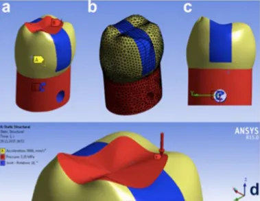
A finite element (FE) model of a mandibular first molar with inlay restoration, containing 45,678 tetrahedron elements, was created from CT images of a real tooth using a FEA (ANSYS, Inc. Canonsburg, PA, USA) (Figure 1(a–d)). Ideal adhesion was assumed between the tooth and the restoration. Occlusal load was simulated to apply pressure onto the tooth (Figure 2(a–d)). Force was applied to the model as an occlusal load in different magnitudes between 10 and 130 kg and at varying angles ranging from 0° to 15° (Figure 2(a–d)). The assumption of linear elastic isotropic material behaviour as a potential simplification for the complexity of FEA simulations was pursued, assuming material properties of enamel, dentin and filling materials as isotropic and linearly elastic (Table 1). Since the pulp is much softer than the other tissues or materials, it was excluded from the FEA model in order to simplify the analysis.[25] Maximum shear stress distribution was calculated within enamel, dentin, inlay material and at the surfaces between the inlay and the cavity walls.
Initially, FEA identified the most highly stressed regions within the restored tooth, inlay and along the tooth–restoration interface. Based on these regions, response surface opti-mization (RSO) was established.
Figure 1. geometry of (a) the whole model, (b) dentin, (c) enamel, (d) inlay.
Figure 2. geometry of (a) fixed surface, (b) finite element model, (c) rotation angle, (d) point of force applied on the model.
Table 1. Mechanical properties of tooth and inlay restoration materials.
Young modulus (gPa) Poisson’s ratio
enamel 84 0.33
dentin 18.6 0.31
resin composite 20 0.35
glass ceramic 90 0.3
Response surface optimization
For the present work, RSO was implemented into the finite element package (ANSYS) in order to design cavity shapes with more favourable interfacial stresses for inlay restorations under occlusal loading. Cavity depth (2–5 mm) and width (2–4 mm), force vector (0–15°) and force magnitude (10–130 kg) were considered as independent parameters for RSO cal-culations. A total of 25 different simulations were made according to the orthogonal array of four parameters, namely the depth and height of the cavity, force vector and magnitude.
Results
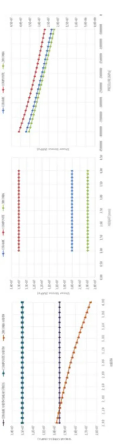
The highest maximum von Mises stress values were found at the interfaces for the resin composite and the lowest for zirconia inlay according to cavity width and depth and force magnitude parameters (Figure 3(a–c)). Interfacial shear stresses remained constant with the increasing cavity depth, thus this parameter could be considered negligible in all three materials. Shear stresses did not change with respect to the width in ceramic and resin composite materials but it decreased in zirconia inlay and it decreased with decreasing pressure in all materials.
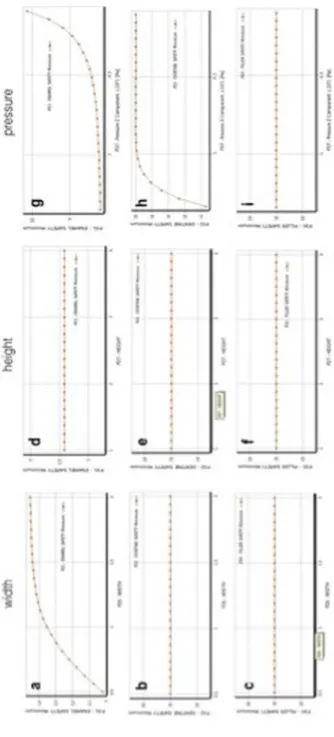
Safety factor describes the capacity of a system to bear forces beyond the expected or actual loads. In dentistry, factor of safety of 1.0 is commonly used for the dental structure or materials. Values below 1, can be considered biomechanically under risk. Safety factor calculated using RSO for the inlay, enamel and dentin in 25 different simulations indicated that force vector was the most effective factor on mechanical safety of the dentin, enamel and inlay (Table 2). In most simulation, safety factor of the inlay and tooth structure were below the mechanical limits when the force were angulated. The effect of cavity depth and width, and force magnitude showed that the increase in the cavity width did not affect the dentin and inlay safety factors but did increase safety factor of enamel (Figure 4). Depth of the cavity did not have any effect on the safety factor of all materials. Safety factor of the dentin and enamel was positively affected with the increase in isthmus width. Increasing the depth of cavity affected the safety factor of both inlay and dentin positively but not the enamel. Decrease in force magnitude increased the safety factors of both enamel and dentin (Figure 5). Safety factor of dentin, enamel and inlay were negatively affected with the increased force angulation but not by the force magnitude.
Discussion
This simulation study was undertaken in order to investigate the effect of three different inlay materials (composite, glass ceramic, zirconia), cavity design parameters (isthmus width and depth) and different force vectors and magnitudes on the stress distribution within MOD inlays and the remaining enamel and dentin and to suggest the optimum material. Based on the results of this study, since zirconia presented better performance under applied force showing reduced stress values in interfacial surfaces compared to other restorative materials, the first hypothesis could not be accepted. The increase in isthmus width decreased maximum interfacial shear stress values in zirconia MOD inlay but the increase in cavity depth did not increase the shear stress in MOD inlays made of all three materials. Thus, the second hypothesis could be partially accepted.
Figur
e 3.
eff
ec
t of (a) width, (b) heigh
t and ( c) pr essur e on shear str ess f or c er amic , c omposit e and zir conia, r espec tiv ely . n ot e tha t shear str
ess does not change with
respec t t o width of r esin composit e and cer amic but it decr eases sig nifican tly with incr easing width in zir conia. shear str ess decr eases with decr easing pr essur e for ma terials .
In dental research, FEA has been widely used to understand the mechanical behaviour of restored teeth.[31] FEA simulations could be considered efficient with lower costs and exhibits less risk, compared to experiments on real teeth or in patients. The method also enables the shape optimization process. The values from FEA are presented as stresses distributed in the structures under investigation where the results are expressed as maxi-mum and minimaxi-mum principal stresses, von Mises maximal stress.[32,33] This is associated with the fact that the normal criterion for the most engineering analyses deals with ductile materials such as steel and aluminium.[34] In fact, von Mises criterion is only valid for the ductile materials with equal compressive or tensile strength. However, materials exhibiting brittle behaviour such as ceramics, cements or resin composites present reported values of compressive strength significantly greater than tensile strength.[35] Positive and negative values signify that the corresponding regions are subjected to tensile or compressive stresses. [36] Hence, it is not possible to implement the results from FEA directly to a clinical situa-tion but it has to design the model in such a way that it mimics the real situasitua-tion as closely as possible. FEA analysis must be interpreted with a certain amount of caution. Most of the studies to date modelled dental structures as isotropic and not orthotropic.[18,26,37] On the other hand, FEA model represents a static situation at the moment of load application and not an actual clinical situation. In reality, the loading of the structure is more dynamic and cyclic. The materials of the various tooth structures were assumed to be isotropic, homogenous and elastic, and that they remain such under applied loads. Therefore, in this study, a non-linear elastic–plastic material model was used instead of linear model.[16]
In this simulation study, axial load between 10 and 130 kg was applied to the occlusal surface. The load represented approximately the average of the maximum bite forces in the Table 2. input parameters and fea results for orthogonal array.
case
Width
(mm) height (mm) Joint – rota-tion angle (degree)
Pressure Z component
(Pa)
Dentine
safety Enamel safety safetyFiller shear stress Maximum (Pa) 1 1.25 2.50 7.50 −7.20e+06 1.15 0.01 0.20 5.51e+08 2 0.50 2.50 7.50 −7.20e+06 0.05 0.01 0.39 7.07e+08 3 2.00 2.50 7.50 −7.20e+06 0.56 0.01 0.16 5.75e+08 4 1.25 1.00 7.50 −7.20e+06 0.65 0.01 0.30 6.21e+08 5 1.25 4.00 7.50 −7.20e+06 0.37 0.01 0.34 3.22e+08 6 1.25 2.50 0.00 −7.20e+06 15.00 1.57 15.00 6.14e+06 7 1.25 2.50 15.00 −7.20e+06 0.57 0.01 0.10 1.10e+09 8 1.25 2.50 7.50 −1.34e+07 1.17 0.01 0.21 5.50e+08 9 1.25 2.50 7.50 −1.00e+06 1.14 0.01 0.20 5.51e+08 10 0.72 1.44 2.22 −1.16e+07 1.15 0.02 1.12 1.05e+09 11 1.78 1.44 2.22 −1.16e+07 0.16 0.03 1.17 1.67e+08 12 0.72 3.56 2.22 −1.16e+07 1.20 0.02 1.32 1.04e+09 13 1.78 3.56 2.22 −1.16e+07 0.17 0.03 1.63 1.32e+08 14 0.72 1.44 12.78 −1.16e+07 0.19 0.00 0.20 6.07e+09 15 1.78 1.44 12.78 −1.16e+07 0.02 0.00 0.17 1.14e+09 16 0.72 3.56 12.78 −1.16e+07 0.19 0.00 0.23 6.02e+09 17 1.78 3.56 12.78 −1.16e+07 0.03 0.01 0.28 7.75e+08 18 0.72 1.44 2.22 −2.83e+06 1.10 0.02 1.13 1.05e+09 19 1.78 1.44 2.22 −2.83e+06 0.16 0.03 1.23 1.58e+08 20 0.72 3.56 2.22 −2.83e+06 1.13 0.02 1.33 1.04e+09 21 1.78 3.56 2.22 −2.83e+06 0.16 0.03 1.58 1.38e+08 22 0.72 1.44 12.78 −2.83e+06 0.19 0.00 0.20 6.08e+09 23 1.78 1.44 12.78 −2.83e+06 0.03 0.01 0.22 8.93e+08 24 0.72 3.56 12.78 −2.83e+06 0.19 0.00 0.23 6.02e+09 25 1.78 3.56 12.78 −2.83e+06 0.03 0.01 0.27 7.94e+08
Figur e 4. eff ec t of (a– c) width, ( d–f ) heigh t and (g–i) pr essur e on enamel , den
tin and inla
y saf et y, r espec tiv ely .
premolar region.[38] It should be noted that a wide range of bite force have been reported in the literature (131–608 N), and the measured biting forces appear to be related to the measuring method, gender and age of the individual.[4,39,40] The choice of the applied load could affect the size and shape of the optimized cavity design.[19]
The use of different materials for restoration substantially modifies the stress distribution in an originally healthy tooth. The difference between the elastic modulus of tooth and restorative material may be a source of stress in the dental structures. If the stress exceeds the yield strength of the materials, fracture of the restorative materials or the tooth may occur. The occlusal force leaning against the tooth axis causes the structure to bend, and the higher tensile stresses are produced. The oblique force loading on the dental structure is the major cause of dental damage and further attention should be paid to the importance of the occlusal adjustment. Many detrimental effects during restorative procedures are reported due to lack of understanding of biomechanical principles underlying treatment. [41,42] Nevertheless, the purpose of using products that have mechanical properties closer to dentin and enamel and obtaining best resistance and retention of the restoration would eliminate dislodgement of the restoration during occluding forces, simultaneously pro-tecting the remaining tooth structure.[41] Typically, two mechanisms operate and cause failure, one being the lateral excursive movements resulting in lateral cuspal movements that generate tensile stresses along tooth restoration interface, and the other heavy forces in centric occlusion that cause vertical deformation on the tooth leading to compressive and shear stresses.[16] The presence of an occlusal restoration weakens the tooth structure and increases the stresses.
In this study, the increase in isthmus width decreased maximum stress values in zirco-nia inlay but the increase in cavity depth did not increase the shear stress in MOD inlays made of all three materials. These findings are contradictory to a previous report where the opposite was reported.[43] The differences in materials chosen and their mechanical properties selected during modelling might have affected the discrepancy.
of utmost tissue conservation and aesthetics. The choice of ceramics as an enamel replace-ment is advocated [44] and their stability relies primarily on the strength and thickness of the material [45] along with effective bonding to the underlying dental substrate,[46] mimicking the function of the dentino-enamel junction.[47] Also, the development of ceramics that are stronger (such as lithium disilicate glass ceramic) but still etchable and machinable has extended the indications for bonded ceramic restorations.[11] The performance of resin composite resins through a superior bond between the different phases, enabling appro-priate stress transfer were further improved after various post-polymerization procedures. [48] Generally, resin composite materials with their low elastic modulus are expected to better absorb functional stresses through deformation.[49] Interestingly however, in this study, zirconia, when used as a MOD inlay material, with its high elastic modulus presented better performance in that it transmitted less stress to enamel and dentin. This could be explained on the grounds that the material itself absorbed the applied magnitude of load before it was transmitted to the surrounding dental tissues. The adhesion of zirconia to the dental tissues is not ideal, whereas in this study ideal conditions were simulated. This aspect should be further investigated focusing on the interface between the zirconia and enamel/dentin complex.
One study showed that increased depth and width of the cavity and lateral loading force increases the peak stress of tooth with inlays. Similarly, present study domonstrated negative effect of angulated force on the safety factor of both tooth and inlay.[50]
Notably, FEA simulation conditions do not simulate the intraoral conditions completely. The restorations are subjected to cyclic loading in the mastication system and the physical properties of the actual materials tested may change over time in the aggressive oral envi-ronment. Thus, the results of computer simulations should be coupled with clinical findings and the results could be used for setting indications especially for worse-case conditions in clinical situations.
Conclusions
From this study, the following could be concluded:
(1) The increase in isthmus width decreased maximum von Misses stresses in MOD inlays made of resin composite, ceramic and zirconia.
(2) The increase in cavity depth did not increase the shear stress in MOD inlays made of all three materials.
(3) Zirconia as an inlay material presented better performance under applied force owing to the reduced stress values in the tooth structure compared to other restor-ative materials. Materials with lower Young Moduli created more stress to the tooth structure.
Clinical relevance
MOD inlays made of zirconia may transmit less stress to the surrounding enamel and dentin under 10–130-kg occlusal loading simulation. Increase in cavity depth from 2 to 5 mm may not increase the shear stress but increase in isthmus width from 2 to 4 mm may be more detrimental for the MOD inlays made of CAD/CAM resin composite, ceramic and zirconia.
Conflict of interest
The authors did not have any commercial interest in any of the materials used in this study.
ORCID
Bülent Ekici http://orcid.org/0000-0001-8967-0649
Emir Yuzbasioglu http://orcid.org/0000-0001-5348-6954
References
[1] Fron Chabouis H, Smail Faugeron V, Attal JP. Clinical efficacy of composite versus ceramic inlays and onlays: a systematic review. Dent Mater. 2013;29:1209–1218.
[2] Zhang YR, Du W, Zhou XD, et al. Review of research on the mechanical properties of the human tooth. Int. J. Oral Sci. 2014;6:61–69.
[3] Yahyazadehfar M, Ivancik J, Majd H, et al. On the mechanics of fatigue and fracture in teeth. Appl. Mech. Rev. 2014;66:0308031–3080319.
[4] Rezaei SMM, Heidarifar H, Arezodar FF, et al. Influence of connector width on the stress distribution of posterior bridges under loading. J. Dent. 2011;8:67–74.
[5] Hamza TA, Ezzat HA, El-Hossary MM, et al. Accuracy of ceramic restorations made with two CAD/CAM systems. J. Prosthetic Dent. 2013;109:83–87.
[6] Hübsch PF, Middleton J, Knox J. A finite element analysis of the stress at the restoration tooth interface comparing inlays and bulk fillings. Biomaterials. 2000;21:1015–1019.
[7] Dejak B, Mlotkowski A, Romanowicz M. Strength estimation of different designs of ceramic inlays and onlays in molars based on the Tsai-Wu failure criterion. J. Prosthetic Dent.
2007;98:89–100.
[8] Holberg C, Rudzki-Janson I, Wichelhaus A, et al. Ceramic inlays: is the inlay thickness an important factor influencing the fracture risk? J. Dent. 2013;41:628–635.
[9] Zaruba M, Kasper R, Kazama R, et al. Marginal adaptation of ceramic and composite inlays in minimally invasive mod cavities. Clin. Oral Invest. 2014;18:579–587.
[10] Peutzfeldt A, Asmussen E. The effect of postcuring on quantity of remaining double bonds, mechanical properties, and in vitro wear of two resin composites. J. Dent. 2000;28:447–452. [11] Schlichting LH, Maia HP, Baratieri LN, et al. Novel-design ultra-thin CAD/CAM composite
resin and ceramic occlusal veneers for the treatment of severe dental erosion. J. Prosthetic Dent. 2011;105:217–226.
[12] Al-Amleh B, Lyons K, Swain M. Clinical trials in zirconia: a systematic review. J. Oral Rehabil.
2010;37:641–652.
[13] Ma L, Guess PC, Zhang Y. Load-bearing properties of minimal-invasive monolithic lithium disilicate and zirconia occlusal onlays: finite element and theoretical analyses. Dental Mater.
2013;29:742–751.
[14] Bremer BD, Geurtsen W. Molar fracture resistance after adhesive restoration with ceramic inlays or resin-based composites. Am J Dent. 2001;14:216–220.
[15] Liu X, Fok A, Li H. Influence of restorative material and proximal cavity design on the fracture resistance of MOD inlay restoration. Dental Mater. 2014;30:327–333.
[16] Shi L, Fok ASL, Qualtrough A. A two stage shape optimization process for cavity preparation. Dent. Mater. 2008;24:1444–1453.
[17] Yamanel K, ÇAGLAR A, Gülsahi K, et al. Effects of different ceramic and composite materials on stress distribution in inlay and onlay cavities: 3-D finite element analysis. Dent. Mater. J.
2009;28:661–670.
[18] Campos RE, Soares CJ, Quagliatto PS, et al. In vitro study of fracture load and fracture pattern of ceramic crowns: a finite element and fractography analysis. J. Prosthodontics. 2011;20:447–455. [19] Borcic J, Braut A. Finite element analysis in dental medicine, finite element analysis – new
posterior inlay and onlay fixed partial dentures. J. Dent. 2012;40:48–56.
[21] Magne P, Stanley K, Schlichting LH. Modeling of ultrathin occlusal veneers. Dent. Mater.
2012;28:777–782.
[22] Holberg C, Winterhalder P, Wichelhaus A, et al. Fracture risk of lithium-disilicate ceramic inlays: a finite element analysis. Dent. Mater. 2013;29:1244–1250.
[23] Chun K, Choi H, Lee J. Comparison of mechanical property and role between enamel and dentin in the human teeth. J. Dent. Biomech. 2014;5:1758736014520809.
[24] Ausiello P, Rengo S, Davidson CL, et al. Stress distributions in adhesively cemented ceramic and resin-composite Class II inlay restorations: a 3D-FEA study. Dent. Mater. 2004;20:862–872. [25] Dejak B, Mlotkowski A. Three-dimensional finite element analysis of strength and adhesion
of composite resin versus ceramic inlays in molars. J. Prosthetic Dent. 2008;99:131–140. [26] Jiang W, Bo H, Yongchun G, et al. Stress distribution in molars restored with inlays or onlays
with or without endodontic treatment: a three dimensional finite element analysis. J. Prosthetic Dent. 2010;103:6–12.
[27] Magne P, Belser UC. Porcelain versus composite inlays/onlays: effects of mechanical loads on stress distribution, adhesion, and crown flexure. Int. J. Periodontics Restorative Dent.
2003;23:543–555.
[28] Farah JW, Dennison JB, Powers JM. Effects of design on stress distribution of intracoronal gold restorations. J. Am Dent. Assoc. 1977;94:1151–1154.
[29] Manhart J, Mehl A, Obermeier T, et al. Finite element study on stress distribution in dependence on cavity width and materials properties. In: Academy of dental materials: proceedings of conference on clinically appropriate alternatives to amalgam: biophysical factors in restorative decision-making. Vol. 9. 1996 Oct 30–Nov 2; Munich, Germany. p. 269.
[30] Khera SC, Goel VK, Chen RC, et al. Parameters of MOD cavity preparations: a 3-D FEM study, Part 2. Oper. Dent. 1991;16:42–54.
[31] Romeed SA, Fok SL, Wilson NH. A comparison of 2D and 3D finite element analysis of a restored tooth. J. Oral Rehabil. 2006;33:209–215.
[32] Sorrentino R, Aversa R, Ferro V, et al. Three-dimensional finite element analysis of strain and stress distributions in endodontically treated maxillary central incisors restored with diferent post, core and crown materials. Dent. Mater. 2007;23:983–993.
[33] González-Lluch C, Rodríguez-Cervantes PJ, Sancho-Bru JL, et al. Influence of material and diameter of pre-fabricated posts on maxillary central incisors restored with crown. J. Oral Rehabil. 2009;36:737–747.
[34] Perez-Gonzalez A, Iserte-Vilar JL, Gonzalez-Lluch C. Biomed. Eng. [cited 2012 Mar 10]. Available from: http://www.biomedical-engineering-online.com/content/10/1/44
[35] Craig R, Powers JM. Restorative dental materials. St Louis: Mosby; 2002. p. 11.
[36] Lang L, Wang RF. Validation of finite element analysis in dental ceramics research. J. Prosthetic Dent. 2001;86:650–654.
[37] Dos Santos MBF, Silva Neto JP, Consani RLX, et al. Three-dimensional finite element analysis of stress distribution in peri-implant bone with relined dentures and different heights of healing caps. J. Oral Rehabil. 2011;38:691–696.
[38] Ferrario VF, Sforza C, Serrao G, et al. Single tooth bite forces in healthy young adults. J. Oral Rehabil. 2004;31:18–22.
[39] Shinogaya T, Bakke M, Thomsen CE, et al. Bite force and occlusal load in healthy young subjects – a methodological study. Eur. J. Prosthodont. Restor. Dent. 2000;8:11–15.
[40] Shinogaya T, Bakke M, Thomsen CE, et al. Effects of ethnicity, gender and age on clenching force and load distribution. Clin. Oral Invest. 2001;5:63–68.
[41] Ricardo J. Influence of the remaining coronal structure on the resistance of teeth with intraradicular retainer. Braz. Dent. J. 2005;16:197–201.
[42] Aggarwal S, Garg V. Finite element analysis of stress concentration in three popular brands of fiber posts systems used for maxillary central incisor teeth. J. Conserv. Dent. 2011;14:293–296. [43] Lee MR, Cho BH, Son HH, et al. Influence of cavity dimension and restoration methods on
[44] Magne P. Composite resins and bonded porcelain: the postamalgam era? J. Calif. Dent. Assoc.
2006;34:135–147.
[45] Manhart J, Chen H, Hamm G, et al. Buonocore memorial lecture. review of the clinical survival of direct and indirect restorations in posterior teeth of the permanent dentition. Oper. Dent.
2004;29:481–508.
[46] Bindl A, Mormann WH. Survival rate of mono-ceramic and ceramic-core CAD/CAM-generated anterior crowns over 2–5 years. Eur. J. Oral Sci. 2004;112:197–204.
[47] Magne P, Belser U. Understanding the intact tooth and the biomimetic principle. In: Magne P, Belser U, editors. Bonded porcelain restorations in the anterior dentition: a biomimetic approach. Chicago, IL: Quintessence; 2002. p. 23–55.
[48] Leinfelder KF. Indirect posterior composite resins. Compend. Contin. Educ. Dent. 2005;26: 495–503.
[49] Magne P, Perakis N, Belser UC, et al. Stress distribution of inlay-anchored adhesive fixed partial dentures: a finite element analysis of the influence of restorative materials and abutment preparation design. J. Prosthetic Dent. 2002;87:516–528.
[50] Zhang L, Lu Y, Yang BS, et al. The finite element analysis of stress distrubution in different size of MO cavities restored with composite resin inlays. Shanghai Kou Qiang Yi Xue. 2015;24: 170–176.