Nonlinear Equivalent Circuit Model for Circular
CMUTs in Uncollapsed and Collapsed Mode
Elif Aydogdu
∗‡, Alper Ozgurluk
∗, H. Kagan Oguz
∗, Abdullah Atalar
∗, Coskun Kocabas
†and Hayrettin Koymen
∗ ∗Bilkent University, Electrical and Electronics Engineering Department, Ankara, 06800 TURKEY†Bilkent University, Physics Department, Ankara, 06800 TURKEY ‡e-mail: [email protected]
Abstract—An equivalent electrical circuit model valid for
collapsed mode operation of CMUT is described. The across and through variables of the circuit model are chosen to be rms force and rms displacement over the surface of the CMUT membrane. The relation between rms displacement and applied voltage is obtained through analytical calculations utilizing the exact force distribution. The radiation impedance of collapsed mode CMUT is included as a load impedance in the circuit model. The resulting equivalent circuit is merged with uncollapsed mode model, to obtain a simulation tool that covers the whole operation range of CMUT.
I. INTRODUCTION
Equivalent electrical circuit modelling of CMUT mechanics is a useful alternative to FEM, with its ease and speed in design and simulation steps. Simulations of large arrays of CMUTs are very cumbersome with FEM, if not impossible. With equivalent circuit approach, the simulation time reduces significantly and hence very large arrays can be handled. The only issue is the accuracy of the model that has to be overcome to replace FEM modelling.
In [1], the equivalent circuit model for uncollapsed mode operation was corrected considering energy conservation. The across variable, force, was redefined as the rate of energy change with respect to rms displacement. This revision in-creased accuracy considerably. Together with self and mutual radiation impedance calculations, the circuit model is a reliable simulator of uncollapsed CMUT operation.
A collapsed mode CMUT model was previously presented in [2]. However, it needs to be improved as it predicts the contact radius and snapback voltage inaccurately. The reason of inaccuracy is the uniform force distribution assumption of Timoshenko’s equation[3]. The model also lacks the radiation impedance model of collapsed CMUTs.
In this work, we aim to develop an accurate circuit model for a collapsed mode CMUT cell. To achieve this goal, the col-lapsed membrane compliance and rms displacement-electrical force relationship are analytically calculated, employing the exact electrical force distribution over the membrane. Obtained results are adapted to the equivalent electrical circuit model seen in Fig. 1. The radiation impedance of the collapsed mode CMUT is utilized in the model for the first time.
Fig. 1. Equivalent electrical circuit representation of CMUT. The rms velocity over the membrane is represented by the current and the rms force is represented by the voltage.
II. EQUIVALENTELECTRICALCIRCUITMODEL OF
COLLAPSEDMODECMUT
A. Mechanics of Collapsed Mode CMUT
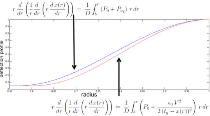
For a collapsed membrane, the nonuniformity in electrical force distribution becomes so intense that a uniform force approximation is no longer valid. With this approximation, the calculated contact radius and snapback voltage turn out to be erroneous as seen on upper curve of Fig. 2.
Fig. 2. Actual deflection profile (lower curve) compared to the one calculated by the uniform-force approximation (upper curve)
In this work, the electrical force term is included in the shear force equation of Timoshenko[3], in order to consider the high electrical force, just around the collapse point. The
987
978-1-4673-4562-0/12/$31.00 ©2012 IEEE 2012 IEEE International Ultrasonics Symposium Proceedings 10.1109/ULTSYM.2012.0247
equation becomes; r d dr ( 1 r d dr ( rd x(r) dr )) = 1 D ∫ r b ( P0+ ϵ0V2 2 (tg− x(r))2 ) rdr
where r stands for the radius variable, x(r) is the deflection at radius r, D is the flexural rigidity, b is the contact radius,
P0is the ambient pressure and the second term in the integral
stands for the electrical force intensity at radius r > b. As this differential equation is not solvable in this form, the electrical force term is approximated by a polynomial. x(r) is calculated in an iterative routine, utilizing a symbolic math package.
r d dr ( 1 r d dr ( rd x(r) dr )) = 1 D ∫ r b ( P0+ ∑ n fnrn ) r dr
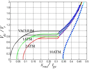
The results of x(r) calculations at different ambient pressure and voltage levels are compared to the FEM results on the static analysis chart of [1]. On this chart, the applied DC volt-age normalized with the collapse voltvolt-age (VDC/Vr) is plotted against the rms displacement normalized with the effective gap height (xrms/tge). Analytical results in the collapse region are shown with dots in Fig. 3. We see that analytical calculations are consistent with FEM results at different pressure levels.
Fig. 3. CMUT biasing chart covering uncollapsed and collapsed regions
Having calculated deflection profile, x(r), for any ambient pressure and applied voltage, corresponding xrms and Cel (electrical capacitance) can be obtained. We can then find numerically dCel/dxrms and Frms = 0.5V2dCel/dxrms (energy conserving electrical force). Unlike the uncollapsed case, the relation between Frms and xrms is nonlinear as shown in Fig.4.
This nonlinear compliance is modelled with a dependent source in the circuit simulation environment. The circuit model adaptation is described in Appendix.
B. Collapsed Mode Radiation Impedance
In order to complete the model, the radiation impedance of collapsed mode CMUT should be included. The radiation
Fig. 4. Normalized spring force of membrane versus normalized rms dis-placement. (tge: effective gap height, Fg: force required to deflect membrane
tgedeep)
impedance is not the same for uncollapsed and collapsed modes, as the velocity profile changes. In the collapsed mode, the velocity profile is as depicted in Fig.5.
Fig. 5. The velocity profile of a collapsed membrane (a: membrane radius,
b: contact radius)
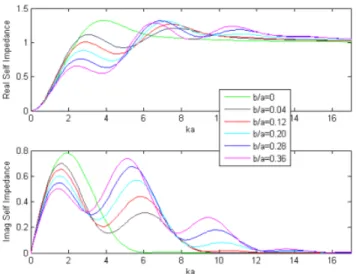
Calculating the velocity profile with Timoshenko’s equa-tions, the radiation impedance is obtained from published results [4]. Normalized radiation impedance as a function of
ka (k is the wavenumber, a is the cell radius) are plotted in
Fig. 6 for different values of contact radius, b. In this Figure,
b/a = 0 curve is equivalent to the uncollapsed mode operation.
As b/a increases, we observe significant change in impedance, unless ka is very high.
The complex radiation impedance data is included in the circuit model by using a table in the frequency domain. In the case of array of collapsed CMUT cells, the mutual impedance of collapsed CMUT cells is also necessary, but this part is left for future work.
III. SIMULATIONS WITHEQUIVALENTCIRCUITMODEL OF
UNCOLLAPSED ANDCOLLAPSEDMODECMUT The uniform force distribution assumption of Timoshenko’s equation induced 10-30% error in the calculation of contact radius in [2]. With the improved model, we first check the consistency in contact radius calculation of FEM and circuit model simulations. CMUT is driven with a pulse of 120-0-120V. The contact radius, b, is plotted as a function of time in Fig. 7. We observe that the results are consistent in time
Fig. 6. The radiation impedance of a collapsed mode CMUT as a function of ka for different degrees of collapse, b/a.
axis, while amplitude difference is observed. The still existing difference at high values of b is due to the flexibility of the membrane material and ground material which is considered in FEM but not in circuit model. The difference at lower values is because of expressing the collapse radius with a single polynomial that only depends on rms displacement. However, it also slightly depends on weight of uniform forces in rms force, and this slight difference implies larger difference in the calculated medium impedance, which is dependent on b. This error can be eliminated with more precise modelling in future studies.
Fig. 7. Contact radius plot of pulse driven CMUT, with FEM (thin) and circuit model (bold) simulations.
The CMUT model is tested for sinusoidally and pulse driven cases. The transient response of a CMUT in water, under 1 atm pressure, is compared to FEM simulations. The simulation parameters are listed in Table I.
In Fig. 8, the CMUT cell is driven by a pulse of 120-0-120V. As the collapse voltage is∼38V, initially the CMUT is collapsed, and it switches to uncollapsed mode when xrms≤ 0.088µm. It is observed that the mechanical response to the electrical pulse is delayed, as the immersion medium applies a significant acoustic reactance to the single CMUT.
Youngs modulus, E 110 GPa Poissons ratio, v 0.27 Dielectric permittivity, ϵr 5.4 Density, ρ 3.1 g/cm3 Membrane Radius, a 30 µm Membrane Thickness, tm 1.2 µm Insulator Thickness, ti 0.4 µm Gap Thickness, tg 0.2 µm TABLE I
PARAMETERS OFCMUTUSED IN SIMULATIONS
Fig. 8. rms velocity of single CMUT (lower plot), driven with the pulse signal in the upper plot. Bold line corresponds to circuit simulation result, thin line is FEM result.
The timing difference in FEM and circuit results again originate from the aforementioned factors. The result becomes very sensitive to differences in medium reactance, for a single CMUT operation, which is not the case for large arrays of CMUTs.
The CMUT is driven sinusoidally with VDC=40V (close to collapse), and VAC=10V at 1MHz. Here we observe frequent transitions between uncollapsed and collapsed modes. The rms displacement is plotted in Fig. 9. Although the DC voltage collapses the membrane, rms motion in uncollapsed region is larger than collapsed region. This tells us that same amount of power is stored in collapsed membrane with less displacement. The circuit model (dashed line) is successful at predicting the whole operation as confirmed by FEM (continuous line).
Fig. 9. rms displacement of single CMUT (lower plot), driven with the sinusoidal signal in the upper plot. Dashed line corresponds to circuit simulation result.
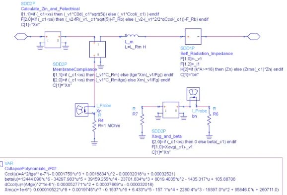
Fig. 10. The equivalent electrical circuit representation of single CMUT in Advanced Design System. The acoustic loading of medium is also included. Except mass of the membrane, all the electrical and mechanical relations are expressed inside controlled sources. The port on the left is the electrical port.
IV. CONCLUSION
With the model of a CMUT cell, we carried out simulations of sinusoidally and pulse driven cases. At the first step of modelling whole operation of CMUT in uncollapsed and collapsed regions, the results are consistent with FEM simula-tions, with some differences. Those differences originate from simplifications in the initial model, which will be improved in the future. Stiffness of ground material, and the instantaneous weight of uniformly distributed forces in rms force profile should be considered to increase accuracy.
Having an accurate model for the collapsed and uncollapsed mode operation of CMUT, we end up with a fast and reliable CMUT simulator. It predicts both small and large signal CMUT behavior in any excitation regime. In future studies, the mutual impedance of the collapsed mode CMUTs will be included to the model, enabling simulation of very large arrays of CMUTs, which are impossible to simulate in FEM because of the excessive size of the problem.
APPENDIX
The circuit model is adapted to ADS (Advanced Design System), through symbolically defined devices utilizing non-linear equations. Electrical force, Fel, membrane compliance,
xrms/Fspring, contact radius, b(xrms), are all expressed with such polynomial controlled sources as in Fig.10. The self radi-ation impedance value of single CMUT, Zrms, with respect to frequency, is introduced to the model with 15 datasets, each
corresponding to a different collapse radius. A symbolically defined device is used to interpolate between those datasets to obtain required Zrms value dynamically.
The collapsed mode CMUT model is merged with uncol-lapsed mode model through “if − else” conditions. As the force and profile close to snapback (b/a = 0) in uncollapsed region, is also calculated with Eq. 1, continuous transition between collapsed and uncollapsed regions was insured.
REFERENCES
[1] H.Koymen, A.Atalar, E.Aydogdu, C.Kocabas, H.K.Oguz, S.Olcum, A.Ozgurluk, and A.Unlugedik, “An improved lumped element nonlinear circuit model for a circular CMUT cell,” IEEE Transactions on
Ultra-sonics, Ferroelectrics, and Frequency control, vol. 59, pp. 1791–1799,
2012.
[2] S.Olcum, Y.Yamaner, A.Bozkurt, H.Koymen, and A.Atalar, “An equiva-lent circuit model for transmitting capacitive micromachined ultrasonic transducers in collapse mode,” IEEE Transactions on Ultrasonics,
Ferro-electrics, and Frequency Control, vol. 58, pp. 1468–1476, 2011.
[3] S. Timoshenko and S. W. Woinowsky-Krieger, Theory of Plates And
Shells. NY: McGraw Hill, 1959.
[4] A.Ozgurluk, A.Atalar, H.Koymen, and S.Olcum, “Radiation impedance of an array of circular capacitive micromachined ultrasonic transducers in collapsed state,” in Proceedings of the IEEE Ultrasonics Symposium,
Orlando, FL, 2011.