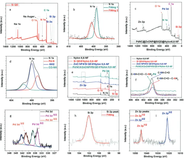
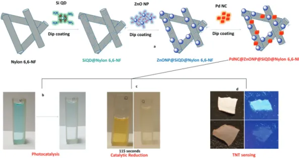
Multifunctional electrospun polymeric nanofibrous mats for catalytic reduction, photocatalysis and sensing
Tam metin
Şekil

Benzer Belgeler
Two 3D single encounter scenarios are designed to schematically show the performance of pilots: 1) 1st scenario consists of two manned aircraft flying with constant speeds in
Lipschitz class, matrix transform, modulus of continuity, Mucken- houpt class, N¨ orlund transform, weighted Lebesgue space.... Proofs of the main results Proof of
The purpose of this work was to investigate (1) the time-dependent rheological behavior of kaolinite-silicon oil pastes and (2) the influences of die dimensions, particle
Lynd to direct a study of New Haven and of child-rearing practices within this commu- nity; the formulation by May and Dollard of an approach stressing the study of human
This note is concerned with the problem of studying the degenerations of fibered surfaces via the degenerations of the base curve and the fibers. Lemma 3 and the discussion
In this section we derive approximate robust counterparts for linear least squares problems in three cases: (1) (A, b) is subject to unknown but bounded perturbation measured
In this study, we will construct an optimal trading strategy for an American option holder under the assumption that stock price follows discrete time discrete state triple random
ABSTRACT: E fficient nonradiative energy transfer is re- ported in an inorganic/organic thin film that consists of a CdSe/ZnS core/shell colloidal quantum dot (QD) layer interfaced with
