YASAR UNIVERSITY
GRADUATE SCHOOL OF NATURAL AND APPLIED SCIENCES
MASTER THESIS
DESIGN AND OPTIMIZATION OF COMPACT
MICROSTRIP PATCH ANTENNAS HAVING BROKEN
LOOP FOR UHF RFID READER APPLICATION
Gonca EŞTÜRK
Thesis Advisor: Assoc. Prof. Dr. Mustafa SEÇMEN
Department of Electrical & Electronics Engineering
Presentation Date:08.08.2016
Bornova-İZMİR
iii
ABSTRACT
DESIGN AND OPTIMIZATION OF COMPACT MICROSTRIP PATCH ANTENNAS HAVING BROKEN LOOP FOR UHF RFID READER
APPLICATION
Eştürk, Gonca
MSc in Electrical and Electronics Engineering Supervisor: Assoc. Prof. Dr. Mustafa SEÇMEN
August 2016, 73 pages
RFID (Radio Frequency Identification) is a wireless communication technology, which provides and follows via radio frequency with capable of storing the information label in wireless environment. RFID technolgy, which provides wireless identification and identifier for the objects, was developed around World War II. An RFID system has readers and tags that communicate with each other by radio frequency.
RFID technology comes into increasing use industry as an alternative to the barcode. The advantage of RFID is that it does not require direct contact or line-of-sight scanning. An RFID system consist of three components; an antenna, a tranceiver (often cobined into the reader) and a transponder (the tag). The antenna uses radio frequency waves to transmit a signal that activates the transponder. When transponder is activated, the tag transmits data back to the antenna. The data is used to notify a programmable logic controller to a computer system and stored on a RFID tag, and need a reader. A typical reader is a device that has one or more antennas that emit radio waves and receive signals back from the tag. A typical reader antenna consist of a radio antenna mounted on a substrate.
In this thesis, microstrip patch antennas including a broken loop structure to be used as the reader antenna in RFID systems at the frequency range of ultra high frequency (UHF) are considered. The study contains two type of antennas which are a compact linearly polarized RFID reader antenna and a compact circularly polarized RFID reader antenna. These antennas are smaller in volume as compared to the
iv
standard microstrip antennas by providing a smaller ground plane with the usage of broken loop. These designs are simulated, manufactured and measured.
The linearly polarized version of the produced microstrip patch antenna has the frequency range of 863.8-872.9 MHz and almost 9 MHz bandwidth by providing minimum 10 dB return loss, 3 dBi gain and minimum 15 dB axial ratio. The measurement results of the corresponding manufactured antenna are also highly consistent with the simulation results such that there is only 1% frequency shift which may arise from variation in the dielectric constant of substrate and manufacture errors.
The circularly polarized version of the design antenna has the working frequency range of 868-872 MHz in simulation and 853.1-857.7 MHz in measurement by providing again minimum 10 dB return loss, 0.5 dBi gain but maximum 6 dB axial ratio. The measurement results of this version have the difference of about 2% with the simulations.
In the final part of the thesis, the designed and produced antennas are tested in an application of RFID system containing a reader card, a tag antenna and a reader antenna (the ones designed in this thesis). The test results reveal that the mentioned reader antennas provide RFID communication (make the system work well) within a distance of about 30-35 cm.
Keywords: UHF RFID, reader antenna, microstrip patch antenna, broken loop,
v
ÖZET
UHF RFID OKUYUCU UYGULAMALARI İÇİN KOMPAKT KIRIK HALKA İÇEREN MİKROŞERİT ANTENLERİN TASARIMI ve
OPTİMİZASYONU
Eştürk, Gonca
Yüksek Lisans Elektrik-Elektronik Mühendisliği Bölümü Tez Danışmanı: Doç. Dr. Mustafa SEÇMEN
Ağustos 2016, 73 sayfa
RFID (Radyo frekansı ile tanımlama), kablosuz ortamda bilgi etiketlerini depolayan radyo frekanslarını üretebilen ve takip edebilen bir kablosuz iletişim teknolojisidir. Kablosuz olarak tanımlama yapan ve objeleri tanımlamayı sağlayan RFID teknolojisi ilk olarak İkinci Dünya Savaşı yıllarında geliştirilmiştir. Bir RFID sistemi birbirleriyle radyo frekanslarıyla haberleşebilen okuyuculardan ve etiketlerden oluşmaktadır.
RFID teknlojisi barkod teknolojisinin alternatifi olarak endüstriyel alanda hızla yaygınlaşmaktadır. RFID sistemlerin avantajları ise doğrudan bir temasa ya da görüş mesafasinde bir taramaya ihtiyaç duymamasıdır. Bir RFID sistemi üç bileşenden oluşur; anten, alıcı (genellikle okuyucuyla birleşiktir) ve transponder (etiket). Anten, transponderi aktif hale getirecek olan sinyali ileten radyo frekans dalgaları kullanır. Transponder aktif hale geçtiğinde etiket bilgileri antene geri gönderir. Bu bilgi, programlanabilir mantıksal denetleyiciyi bir bilgisayar sistemine bildirmek için kullanılır. Bu bilgi RFID etikette depolanır ve bir okuyucuya ihtiyaç duyar. Tipik bir okuyucu, radyo dalgaları yayan ve etiketten gelen sinyalleri alabilen bir ya da daha fazla antene sahiptir.
Bu tezde, ultra yüksek frekansta (UHF) radyo frekansıyla tanılama sisteminde bir okuyucu anten olarak kullanılmak üzere bir kırık hal yapısı içeren mikroşerit yama antenleri düşünülmüştür. Bu çalışma, biri kompakt bir doğrusal polarizasyonlu RFID okuyucu anteni diğeri dairesel polarizasyonlu bir kompakt RFID okuyucu anteni olmak üzere iki tip anten içermektedir. Bu antenler, kırık halka yapısı
vi
kullanılması ile daha küçük toprak düzlem sağlayarak standart mikroşerit antenlere göre hacimce daha küçüktür. Bu tasarımlar simüle edilmiş, üretilmiş ve ölçülmüştür.
Üretilen mikroşerit yama antenin doğrusal polarizasyonlu versiyonu 863.8-872.9 MHz frekans aralığına sahiptir ve en az 10 dB geri dönüş kaybı, 3 dBi kazanç ve en az 15 dB eksensel oran sağlayarak yaklaşık 9 MHz’lik banda sahiptir. Bahsedilen antenin ölçüm sonuçları, simülasyon sonuçları ile oldukça tutarlıdır ki dielektrik katsayısındaki değişiklik ve üretim hatalarından kaynaklanabilecek sadece yüzde 1’lik bir frekans kayması vardır.
Tasarlanan antenin dairesel polarizasyonlu hali, yine en az 10 dB geri dönüş kaybı, 0.5 dBi kazanç ama en fazla 6 dB eksensel oran sağlayarak simülasyonda 868-872 MHz, ölçümde 853.1-857.7 MHz frekans bandına sahiptir. Bu versiyonun ölçüm sonuçları, simülasyon sonuçları ile yüzde 2’lik bir farka sahiptir.
Tezin son kısmında üretilen ve tasarlanan antenler; bir okuyucu kartı, bir etiket anteni ve bir okuyucu anteni (tezde tasarlananlar) içeren bir RFID sistem uygulamasında test edilmiştir. Test sonuçları göstermiştir ki değinilen okuyucu antenler yaklaşık 30-35 cm mesafe içinde RFID iletişimi sağlamaktadır (sistemi iyi bir şekilde çalıştırmaktadır).
Anahtar sözcükler: UHF RFID, okuyucu anten, mikroşerit yama anten, kırık halka,
vii
ACKNOWLEDGEMENTS
I would like to thank to my supervisor Assoc. Prof. Dr. Mustafa SEÇMEN for his contribution, guidance and patience during the thesis.
I would like to thank Assist. Prof. Dr. Nalan ÖZKURT for not only being member of the jury, reading and reviewing my thesis but also for the support in the courses of my graduate education at Yasar University.
I would also thank Assist. Prof. Dr. Kağan TOPALLI from Bilkent University for reading, reviewing and being the member of my jury. I am also thankful to him for his precious time and traveling long way from Ankara to Izmir for my thesis defense.
I would like to thank Recep ELMAS who provided of the communication (reader) module in the experimental part of this thesis.
Finally, I would like to thank my Mom, Dad, Sister, Grandparents and my fiance for their love, Support and patience over the years. This thesis is dedicated to them.
viii
TEXT OF OATH
I declare and honestly confirm that my study, titled “Design and Optimization of Compact Microstrip Patch Antennas Having Broken Loop for UHF RFID Reader Application” and presented as a Master Thesis, has been written without applying to any assistance inconsistent with scientific ethics and traditions, that all sources from which I have benefited are listed in the bibliography, and that I have benefited from these sources by means of making references.
ix TABLE OF CONTENTS Page ABSTRACT iii ÖZET v ACKNOWLEDGEMENTS vii
TEXT OF OATH viii
TABLE OF CONTENTS ix
INDEX OF FIGURES xii
INDEX OF TABLES xv
1 INTRODUCTION 1
1.1 Scope of the Thesis 1
1.2 Research Motivation 2
1.3 Thesis Overview and Outline of the Thesis 3
2 INTRODUCTION TO RFID 4
2.1 What is RFID Technology? 4
2.2 The Working Principles of RFID System 8
3 MICROSTRIP PATCH ANTENNA DESIGN 12
x
3.2 Microstrip Patch Antenna Parameters and Factors in the Design 13
3.2.1 Geometry 13
3.2.2 Radiation Mechanism and Radiation Characteristics 14 3.2.3 The Reflection Coefficient and the Characterictic Impedance 16
3.2.4 Return Loss 16
3.2.5 Gain and Radiation Efficiency 16
3.2.6 Polarization 18
3.2.7 Bandwidth 20
3.3 Microstrip Patch Antenna Feed Techniques 21
3.3.1 Probe Feed 21
3.3.2 Microstrip Feed 22
3.3.3 Aperture Coupled Feed 22
4 THE EFFECTS OF ANTENNA PROPERTIES ON THE READ DISTANCE 24
4.1 The Effect of Antenna Gain 24
4.2 The Effect of Antenna Frequency 24
4.3 The Effect of Antenna Polarization 25
5 DESIGN OF AN UHF MICROSTRIP PATCH ANTENNA 27
xi
5.2 Design Procedure and Steps 29
6 DESIGN AND SIMULATION OF RFID READER ANTENNAS 33
6.1 The Proposed UHF RFID Antennas Structure 33
6.2 Simulation and Measurement Results of Linearly Polarized RFID Reader
Antenna Design 40
6.3 Simulation and Measurement Results of Circularly Polarized RFID Reader
Antenna Design 50
7 DESIGN OF EXPERIMENTS FOR THE PROPOSED UHF RFID SYSTEM 58
7.1 Experimental Setup 58
7.2 Experimental Results 63
8 CONCLUSIONS 69
REFERENCES 71
xii
INDEX OF FIGURES
Figure 2.1 Working illustration of RFID system ... 9
Figure 2.2 Geometrical representation of the sinusoidal current wire source ... 10
Figure 3.1 A basic microstrip patch antenna ... 12
Figure 3.2 Different shapes of microstrip patch antenna ... 13
Figure 3.3 A rectangular microstrip patch antenna ... 14
Figure 3.4 The fields on microstrip patch antenna ... 14
Figure 3.5 The surface currents on microstrip patch antenna ... 15
Figure 3.6 A typical antenna radiation pattern ... 15
Figure 3.7 A random linear polarization view ... 18
Figure 3.8 A random circular polarization view ... 19
Figure 3.9 Impedance bandwidth definition ... 20
Figure 3.10 A coaxial feeding view ... 21
Figure 3.11 A microstrip feeding view ... 22
Figure 3.12 Aperture-coupled feed ... 23
Figure 5.1 The dimensional view of microstrip patch antenna ... 27
Figure 5.2 The fringing fields ... 29
xiii
Figure 6.1 CST model of a traditional rectangular patch on Roger RO4003C at 868 MHz ... 34 Figure 6.2 The reflection coefficient (S11 parameter) of the traditional antenna in
Figure 6.1. ... 34 Figure 6.3 (a) Designed linearly polarized patch antenna from top view (b) linearly polarized patch antenna bottom view in CST Microwave Studio ... 36 Figure 6.4 (a) Designed circularly polarized patch antenna from top view (b) circularly polarized patch antenna bottom view ... 39 Figure 6.5 Simulated S11 of the linearly polarized antenna ... 41
Figure 6.6 Gain of linearly polarized microstrip patch antenna ... 42 Figure 6.7 (a) E-plane Realized Gain Pattern (yz plane) (b) H-plane Realized Gain Pattern (xz plane) for linearly polarized antenna ... 43 Figure 6.8 (a) Axial Ratio Pattern (ϕ=0°) (b) Axial Ratio Pattern (ϕ=90°) for linearly polarized antenna ... 45 Figure 6.9 The front and back view of produced linearly polarized UHF RFID reader antenna ... 45 Figure 6.10 The setup for S11 measurement of linearly polarized antenna ... 46
Figure 6.11 S11 measurement and simulation results for linearly polarized antenna . 47
Figure 6.12 Gain measurement setup in Yasar University Antenna and Microwave Laboratory ... 49 Figure 6.13 Simulated S11 of the circularly polarized antenna ... 50
xiv
Figure 6.15 Simulation results for axial ratio pattern at 868 MHz and ϕ=90° ... 52
Figure 6.16 Simulation results for gain radiation pattern at 868 MHz and ϕ=90° ... 53
Figure 6.17 The front and back views of the produced circularly polarized compact UHF RFID reader antenna ... 54
Figure 6.18 S11 results of circularly polarized antenna ... 55
Figure 6.19 Axial Ratio Measurement in Laboratory (a) First step (b) Second step . 56 Figure 7.1 Overview of a passive RFID system ... 58
Figure 7.2 RS500 Reader ... 59
Figure 7.3 Power measurement for RS500 is a communication module ... 61
Figure 7.4 Power level values for RS500 module at different frequencies ... 62
Figure 7.5 Tag antenna used in system tests ... 63
Figure 7.6 The view of reader module and linearly polarized UHF RFID antenna connection ... 64
Figure 7.7 A view of software for RS500 reader module ... 65
Figure 7.8 The measurement of reader antenna’s reading distance ... 65
xv
INDEX OF TABLES
Table 6.1 The parameters of the designed microstrip patch antenna without segmented loop……… 33 Table 6.2 The initial parameters of the designed microstrip patch antenna………… 37 Table 7.1 The Operation Features of RS500………... 60
1
1 INTRODUCTION 1.1 Scope of the Thesis
Radio Frequency Identification (RFID) is used for recognition of the objects or creatures with radio waves in the specific distance and monitoring. RFID tecnology is widely used in the areas such as manufacturing, automotive, textiles, fuel, logistics, in agriculture, health, security. Radio Frequency Identification (RFID), which was developed around World War II, is a technology that provides wireless identification, tracking capability and is more robust than that of a barcode (Ren et. al, 2012). The aim of this study is to design far-field UHF RFID reader antennas with wide radiation areas and long detection distances. The design reason lies in designing reader antennas which are electically big yet capable of offering powerful a good area distribution within its application area.
Generally, the RFID system at low frequency (LF:125 kHz-134 kHz), high frequency (HF:13.56 MHz) and ultra high frequency (UHF: 840 MHz-960 MHz). Globally each country has its own frequency allocation for UHF RFID applications, such as 840.5-844.5 MHz and 920.5-925.5 MHz in China 846-955 MHz in Europe, 902-928 MHz in North and South of America and 952-955 MHz in Japan and so on. The UHF RFID frequency ranges from 840.5-955 MHz.
In this thesis, microstrip patch antenna design to be used as the reader antenna in Radio Frequency Identification systems (RFID in the European UHF frequency range). The design of UHF microstrip patch antenna along with a compact loop antenna presented for mobile ultrahigh frequency (UHF) radio frequency identification is mentioned, and the simulation and measurement results are given. In addition, the core components of the RFID technology, working structure, required parameters for designing efficient reader antenna are mentioned, and it is informed about the advantages provided with the RFID technology. The linearly polarized version of the produced microstrip patch antenna has the frequency range of 863.8-872.9 MHz and 9 MHz bandwidth, and there exists also the design of circularly polarized version. In the literature, circular polarized microstrip patch antenna for UHF RFID studies, although the circular polarized broken ring microstrip antenna for
2
the first time discussed in this statement (Chen H.-D,Kuo S.-H., Sim C.-Y.-D. and Tsai C.-H, 2012).
1.2 Research Motivation
Loop antennas are normally used as reader antennas in the LF and the HF RFID systems (X. Qing, Z. N. Chen, A. Cai, 2007). Whilst a loop antenna is less than half of-a-wavelength at its operating frequency, it provides robust and even magnetic discipline distribution inside the course perpendicular to the surface of the loop. Such characteristic is desirable for the RFID tagging systems. This is because when the loop is of the length less than 0.5 λ, current flows in a single direction. Such current flow produces magnetic fields which are added in the center region of the loop antenna (G. C. Khan, 2009). As a result, the magnetic area distribution at the space enclosed with the aid of the loop is strong and even. Based on types of objects and applications, the inductively coupled near-field operation or electromagnetically coupled far-field operation are used to transform information between reader antenna and tag (Bijaya Shrestha, Atef Elsherbeni, 2011). The tags placed in this area are successfully detected, but, whilst the running frequency of the antenna rises to the UHF band, the antenna physical length greatly decreases. This decrease of region limits the range of tags to be detected at a single study. If the electric length of the conventional loop antenna at the UHF band is enlarged, the loop antenna cannot produce uniform magnetic subject because the ongoing flowing inside the loop functions nulls and section-inversion along the boundary. As a result, the antenna produces relatively weak magnetic field in certain regions of the antenna and this affects the tag detection. Therefore, the design challenge of the far-field UHF RFID reader antenna lies in creating an electrically large reader antenna with strong and uniform magnetic far-field distribution in the interrogation region. The thesis is on manufacturing a reader antenna in UHF band and providing RFID reader with high performance and low cost. Raido frequency identification technology, is a new generation technology that has been widely used in our everyday life, such as security control, library management system, no-stop parking solution, logistic, jewelry management system, identify an object, an animal or person, to enable item-level management, inventory and asset control. In view of this this thesis is promoting more cost-effective rfid reader, so as to contribute and promote this cutting-edge technology forward.
3
1.3 Thesis Overview and Outline of the Thesis
In the thesis, two designs of UHF RFID reader antenna are proposed. The configuration of every layout is given. It is followed by the explanation in the principle of the proposed antenna operation. Then, the antenna layout guidelines are declared. The parametric examine is finished on the proposed antenna. After that, the proposed antenna is being prototyped. The measurement of the antenna prototype is performed to confirm the layout. Afterwards, evaluation between the proposed antennas is given. Finally, concluding comments of proposed antenna are supplied.
This thesis can be examined in the 8 chapters; history, RFID tag antenna design properties and problems, microstrip patch antenna and a compact loop antenna is presented, most used antenna complicated impedance matching techniques and size reduction strategies.
In Chapter 2, the core components of the RFID technology, working structure, required parameters for designing efficient reader antenna are mentioned, and it is informed about the advantages provided with the RFID technology.
Chapter 3 includes that overview of patch antenna design and microstrip patch antenna parameters and factors in the design are given, and design parameters which are necessery for designing, are explained.
Chapter 4 focuses the antenna properties which affect the reading distance as frequency, polarization, gain.
Chapter 5 explains all parameters and properties which are used in the design of an antenna, and give information about resonance frequency and input impedance which are important factors for an antenna.
Chapter 6 gives the design of the proposed antenna structures as well as the corresponding simulation and measuement results for the corresponding antennas.
Chapter 7 presents the test results of a full RFID system by using a reader card, a tag antenna and the reader antennas designed in this thesis. Chapter 8 concludes the thesis.
4
2 INTRODUCTION TO RFID 2.1 What is RFID Technology?
Radio Frequency Identification RFID technology when was developed around World War II, that provides wireless identification, tracking capability, provides identifier for the objects and is more robust than that of a barcode. Radio is a rapidly developing technology that can be used to identify any object wearing an electronic tag by using electromagnetic waves. RFID technology, RFID tag and radio frequency queries are made with a silicon chip to receive and answer, consists of an antenna and coating. This generation has been rapidly developing in lots of services as industries, automotive, textile, fuel oil, logistics, welfare, security system, agriculture and so forth. In RFID system, the reader emits signals via reader antenna. The area and the cohesion of systems are a good deal dependent on the radio frequency which the gadget utilize. The operating frequency can decidedly affect detection area, data receiving-transmitting speed, interoperability, and so on.
The purpose of this system; pass the data to label, to read the information in the label when it is needed. The data in the label can be anything ID as a product, a commodity, a vehicle. To include more detailed information on the label, can be obtained more detailed information about the object or product. Information which read the label and queried to make meaningful are needed on a system. To accomplish this can be used in a data information system or computer.
This system basically consists of two parts; tag and reader parts. Tags are the basic elements of this system. Tags consist of an antenna and small silicon chip. This integrated silicon consists of a radio receiver, memory, logic control, power system and a radio modulator for sending the required answer back to the reader. Tags can be placed directly into the objects (products, packages, vehicles, people, etc.). The required dialog to read recorded information within the chip in the label is carried out via reader and antenna which in the label with radio frequency.
5
The readers are the another basic elements of the RFID systems. RFID reader sends radio energy impulses to the tag and evaluates the answer from the label. The label detects the energy and sends back to answer. This answer could be the serial number and other information. RFID readers are usually active, constantly emit radio energy and to enter a tag into the reading area.
In order to reader communicate to label, the required energy is provided by creating time-varying magnetic field on depending operating frequency. Reader sends that magnetic field mostly via circular framed antenna. When the current flows in a circular frame antenna, the generated magnetic field strength is calculated with;
( ) ⁄ (2.1)
where I= current flowing from the antenna
N= Frame antenna winding number
R= Antenna diameter
X= the distance of the line perpendicular to the plane of the antenna the receiver.
When the current flows in a linear frame antenna, the generated magnetic flux density is calculated with;
( ) (Weber/ ) (2.2)
where I =Current
r: the distance from the center of the wire
6
As a special case given the infinite-length wire where α1=-180⁰ ve α2=0⁰, this magnetic flux density is calculated as
(2.3)
In RFID, when the system works as a near-field system (application), the voltage induced in tag coil is found by Faraday’s Law:
(V) (2.4)
N= Antenna coil winding number
Ψ= Magnetic flux in each winding which is formulated as
∫ (Weber) (2.5)
B= The magnetic fields
S= Winding to the surface area
where B and S is a vector component.
When the system works as a far-field system (application), the resonant frequency on the tag antenna is calculated as
√ (Hertz) (2.6)
Depending on the distance between the reader antenna and tag-induced voltage will change. Accessible working distance is limited because of change this voltage. One of the main parameters of coupling coefficient k;
7
=Magnetic flux through the label coil
= Magnetic flux through the reader coilThe functions of radio frequency energy label that is sent by the reader contains the carrier signal to perform. Energy supply carrier signal label to send back information with reader provides synchronization. Gets the label signal modulates and sends it back to the reader. This sent signals to the reader antenna label are referred to backscatter signals. Reader that is taken by backscatter signals are decoded. The amount of power received by the reader can be roughly calculated by the following equations;
The equation for forward link calculation:
Ptag (dB) = Pt (dB) + Path Loss (dB)+ Gr(dBi) + Gtag(dBi) (2.8)
The equation for reverse link calculation:
Pr (dB) = Ptag (dB)+ Modulation Loss (dB) + Path Loss (dB) (2.9)
where Pt: Reader transmit power (generally at most 1 W)
Ptag: Power incident on tag
Pt: Reader received power
Gr: The reader antenna gain (generally 6 dBi)
Gt: Tag antenna gain (generally 0 dBi)
RFID transponders achieve in different frequency bands. The unique frequency is controlled by the radio regulatory enterprise in each country. The general frequencies for RFID are 125-134 kHz (LF), 13.56 MHz (HF), 400-960 MHz (UHF), and 2.45 or 5.8 GHz (Microwave) (F. T. Ulaby, E. Michielssen, U. Ravaioli, 2010). Although there are different frequencies used, those are the primary ones. In the UHF band, there are two areas of interest, one around 400 MHz (e.g. 433 MHz) and
8
another around 860 – 960 MHz. Each of the frequency bands has blessings and drawbacks for operation. There exists no single frequency for every utility. When the operating frequency of the antenna increases to the UHF band, the perimeter of the loop antenna becomes comparable to the operating wavelength. Therefore, the loop antenna cannot produce a uniform magnetic field any more since the current flowing along the loop features phase-inversion and current nulls along the circumference (X. Qing, C. K. Goh and Z.N. Chen, September 2009).
2.2 The Working Principles of RFID System
RFID system’s communications can be made between a reader which is actually called as transceiver and a tag. Radio frequency identity (RFID) tags are ever growing in use, from the monitoring of additives to the tracking of produce or farm animals throughout processing & manufacturing. They are additionally widely used in the touch-less technology seen today in store and charge cards and banking offerings. With this there was the ever increasing need to lessen the strength required to spark off the RFID tag, even as maximizing the read range. When interrogated by the reader, a tag responds with info regarding identity, still as alternative relevant info looking on the precise application. The tag is, essence, an electrical device commanded by the reader. The practicality and associated capabilities of the RFID tag rely upon two vital attributes: a) whether the tag is of the active or passive type, and b) the tag’s operating frequency. Consequently, passive RFID systems are restricted to short read ranges (between reader and tag) on the order of 30 cm to 3 m, looking on the system's band. RFID system use two types of antenna such as dipole antenna for the reception of electric fields and loop antenna for reception of magnetic fields. The antenna uses a magnetic field known as inductive or near field, which looses its strength after a short distance. Thus, it is suited for RFID applications that allows the RFID transponders to be placed very near to the transceiver (J. Uddin, M. B. I. Reaz, M. A. Hasan, A. N. Nordin, M. I. Ibrahimy, M. A. M. Ali, May 2010).
Figure 2.1 shows how an RFID system works. Once activated by the signal from the tag reader (which acts as both a transmitter and a receiver), the RFID tag responds by transmitting the programmed into its electronic chip. After that, the reader forwards the data it received from the RFID tag to a database that can then match the tag’s identfying serial number to an authorized system.
9
Figure 2.1 Working illustration of RFID system
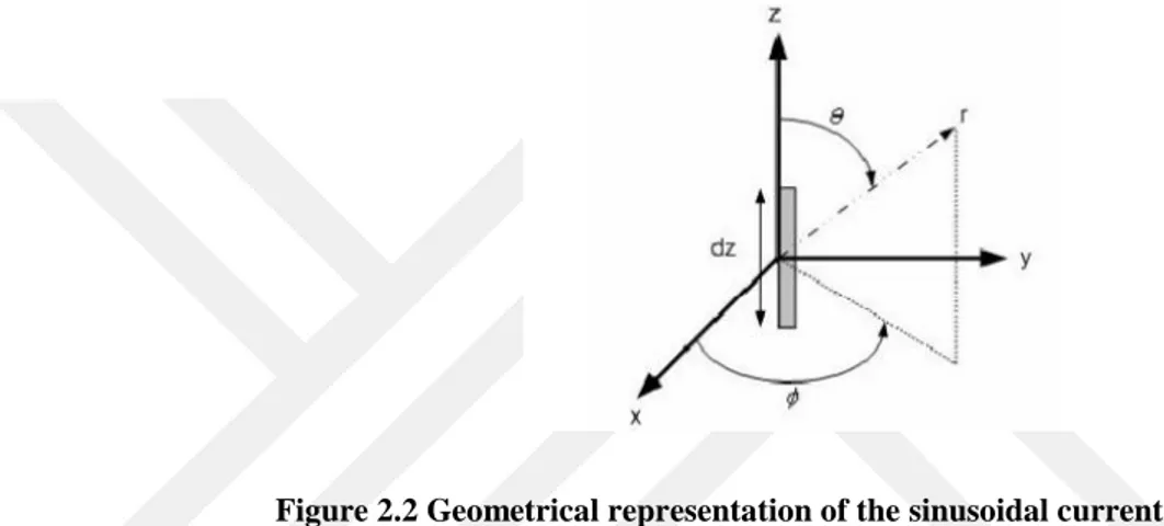
The antenna of the transponder is the best radiating detail which provides the RF communicate hyperlink from the transponder to the interrogator and vice versa. The general expression for the fields from a radiating sinusoidal current wire supply is given below as;
[
√
]
( ) (2.10)
[√ ] ( ) (2.11) [√ ] ( ) (2.12)where; Io = the amplitude of the sinusoidal current electrod source
dz = the sinusoidal current filament source length 2
k wavenumber in free-space
r = radial distance from the sinusoidal current electrod source ω = 2πf , f is the frequency
10 μ = permeability of the medium
ε = permittivity of the medium
The geometry of the sinusoidal current wire supply is displayed in Figure 2.2. The fields surrounding the radiating element can be identified with the equations (2.10), (2.11), (2.12).
Figure 2.2 Geometrical representation of the sinusoidal current wire source
Inside the near-subject, the electromagnetic power strains are shaped transferring outwards from the radiating detail and then back into the radiating element as shown in Figure 2.3;
Figure 2.3 The image of inductively and electromagneticly coupling
A close to-area antenna uses inductive coupling this means that that it uses a magnetic field to energize the RFID tag. Near-field coupling take places within
11
approximately one wavelength of a radiating element. Near-field coupling takes place for RFID applications operating in the LF and HF bands with relatively short reading (S Kalaycı, May 2009). A magnetic field is created inside the near-area that allows the RFID reader’s antenna to energize the tag. The tag then responds by growing a disturbance within the magnetic subject that the reader alternatives up and decodes. On the other hand, a far-field antenna uses capacitive coupling (or propagation coupling) to energize the RFID tag. Capacitive coupling happens while the RFID reader’s antenna propagates RF energy outward and that power is used to energize the tag. The tag then sends lower back a portion of that RF strength to the reader’s antenna as a reaction that is called backscatter.
A far-field antennas come in a huge sort of styles and sizes and generally can examine tags among a few centimeters, up to extra than 9 meters away in ideal conditions. Plenty of alternatives are available when selecting a much-area antenna inclusive of linear or circular polarization, varying advantage, and alternatives for indoor or outdoor use. because of the improved examine region whilst the usage of far-subject antennas, stray tag reads (i.e. analyzing accidental RFID tags) tend to be a not unusual issue.
12
3 MICROSTRIP PATCH ANTENNA DESIGN 3.1 Overview of Microstrip Patch Antenna
Microstrip antenna is composed of a thin metallic patch separated from the conductive ground by a dielectric layer as shown in Figure 3.1. Microstrip antennas are most of the maximum widely used styles of antennas inside the microwave frequency variety, and they're regularly used within the millimeter-wave frequency range as properly. Besides called as patch antennas, microstrip patch antennas consist of a metallic patch of metal that is on top of a grounded dielectric substrate of thickness h, with relative permittivity and permeability εr and μr. There are many
advantages and disadvantage compared to other antennas.
Figure 3.1 A basic microstrip patch antenna
There are many advantages of microstrip antennas as compared to other antennas which can be expressed as
Weights and volumes less than the others
It can be produced easily a large number of with low-cost fabrication Both are linear and circular polarization format allows
They are consistent easily with the Microwave Integrated Circuits (MIC)
The same antenna can be set up to work on more than one frequency
All of these features as well as microstrip antenna has some limitations; Generally the bandwidths are narrower
13 There are many dielectric losses.
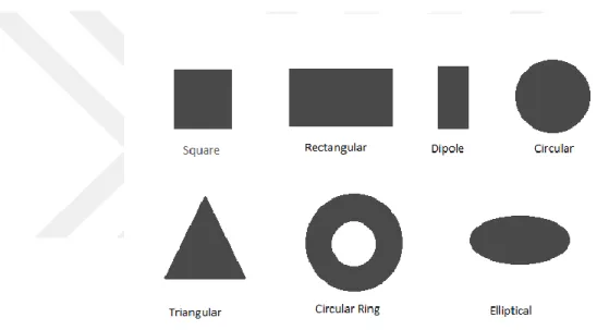
Metallic patch, although the creation in any way, in terms of facilitating the analysis and performance estimates appears to commonly known formats such as rectangle, square, circle or triangle geometry as shown in Figure 3.2. A microstrip antenna in its simplest form consists of a rectangular shape (or other shapes such as circular, triangular, etc.) on top of a substrate backed by a ground plane (J. L. Volkais, 2007).
Figure 3.2 Different shapes of microstrip patch antenna
3.2 Microstrip Patch Antenna Parameters and Factors in the Design 3.2.1 Geometry
Geometry selection antenna is one of the most important factors for designing realistic and useful antenna, after a suitable dielectric substrate choice. A thick dielectric layer provides more power, increases of the radiation power and impedance bandwidth increases. but not useful due to weight, dielectric loss and surface-wave loss. Low dielectric permeability ( ) shows the same effects with thick layer. The thesis has used rectangular metallic patches as given in Figure 3.3. It is the most
14
widely used format because geometrically analysis, is easy, according to the circular shape provides more bandwidth. According to other shapes to more cooperative and compliant physical optimization and the best suited shape for thin dielectric layer.
Figure 3.3 A rectangular microstrip patch antenna
3.2.2 Radiation Mechanism and Radiation Characteristics
Radiation in microstrip antenna is created by electrical field distribution between conductive ground plane and metallic patch. This case can be explained with the distribution of surface currents on the patch as shown in Figure 3.4 and Figure 3.5, respectively. An antenna which is connected to a microwave source such as conducting ground plane, load polarization occur the upper and lower surfaces of metallic patch.
15
Figure 3.5 The surface currents on microstrip patch antenna
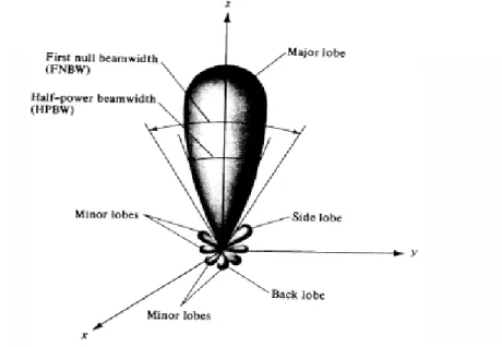
Radiation characteristic is a function of an antenna of power to emit or required power. The characteristic refers to how power is routed. The following illustration in Figure 3.6 shows the general radiation characteristics of an antenna which can be redirected are given. These results can be achieved from the shape;
A transmitter antenna main lobe should be more bigger and longer than other lobe.
Back and minor lobes are unwanted instances. In terms of the transmitter antennas, back and minor lobes are represent the energy spent which is not transferred to the main lobe. They represent noise from transmission environment.
16
3.2.3 The Reflection Coefficient and the Characterictic
Impedance
In high frequency applications, reflection coefficient is an important factor to be reckoned with in microwave transmission line. Each transmission line has a characteristic impedance special of the structure. This impedance is taken generally as 50 Ω. If the line end of any load is not the same value of impedance which is visible from the entrance, the reflection event occurs. This situation is a reflection coefficient for modeling has been defined, and it is equal to the ratio of the outgoing wave voltage and the returned wave voltage.
(3.1)
3.2.4 Return Loss
Return loss is a parameter that the amount of power does not disappear and the payload as reflection. When the mismatch between transmitter and antenna impedance values is higher, the losses more result from standing waves. Return loss in simulation of antenna can be shown in dB in the below formulation as
( ) (3.2)
Γ=0 or RL= can be considered as perfect match of the impedance between antenna and transmitter. In these cases, concluded that failing to back the power reflected image sequence. In practice this results never is currently unavailable. Instead of the use of the antenna and the desired properties, reflection coefficient, and hence the return loss should be taken to acceptable values.
3.2.5 Gain and Radiation Efficiency
Because of being passive structures, antennas don’t have gain of active devices such as amplifiers. Radiation efficiency is defined as a factor that represents antenna gain. Because of the radiation efficiency is always lower than 100%, the antenna gain
17
is always lower than antenna directivity. This efficiency quantifies the losses in the antenna and is defined as the ratio of radiated power (Pr) to input power (Pi). Gain is an important factor that occurred, antenna losses in determining. gain passes through as the concentration ability to an angular space area to antenna power.
(3.3)
where is the efficiency of radiation. Efficiency of radiation is a measure of the rate of losses dielectric and surface wave which related directly with total radiation power, input power, transmission loss and structure. The radiation efficiency is;
(3.4)
For a less lossy dielectric material, transmission loss, , and dielectirc loss , can be neglected. Radiation power for rectangular patch type microstrip antenna, h is the layer thickness, is the free-space wavenumber.
(
)
(
) (3.5)
The waves which are not sent directly due to the losses in antenna, remains to the surface of the child of metallic layers or radiate the other directions. This waves are called the surface-wave and is called the power of this surface wave strength;
( ) ( √ √ ) ( ( ) ) (3.6)
The input power is transformed into radiated power, surface wave power and a small portion is dissipated due to conductor and dielectric losses. Surface waves are guided waves captured within the substrate and partially radiated and reflected back at the substrate edges. Surface waves are more easily excited when materials with higher dielectric constants and/or thicker materials are used. Surface waves are not excited when air dielectric is used. Antenna gain can also be specified using the total
18
efficiency rather than just the radiation efficiency. This total efficiency is a combination of the radiation efficiency and efficiency linked to the impedance matching of the antenna. Orienting the antenna (D) can explained as the energy density in the main lobe. So how much power in the main lobe means that antenna directed extremely well. This is equal to the rate of the density of a given direction of radiation in isotropic antenna. A patch antenna radiates power in certain directions which is desired and we say that the antenna has directivity (usually expressed in dBi). If the antenna had a 100% radiation efficiency, all directivity would be converted to gain. Typical half wave patches have efficiencies well above 90%.
3.2.6 Polarization
Antenna polarization is a very important parameter when choosing and designing an antenna. It helps to have a good clamp of all the condition of this subject. Most communications systems use either vertical, horizontal or circular polarization. Knowing the difference between polarizations and how to maximize their benefit is very important to the antenna user.
Polarization is the direction of wave radiated by the antenna. It is a factor of an electromagnetic wave describing the time varying direction and relative magnitude of the electric field vector (Hasse R., Demir V., Hunsicker W., Kajfez D. and Elsherbeni A., 2008). There are two very common kind of polarization; linear polarization and circular polarization. In Figure 3.7, a random wave propagation characteristics for linear polarization is depicted.
19
Given the spread of the wave radiation on the screen parallel Ex-Hy plane, if get
out of any straight line in any direction, in this case, the polarity of the wave is linear polarization. Here amplitude changing over time but straight line remain constant.
If the projection falls on the screen as given in Figure 3.8 where amplitude fixed but the direction changes over in time, the wave is called circular polarization.
Figure 3.8 A random circular polarization view
In a linear polarization wave, AR= 0 or and electric field x and y components have the same phase ( ); but circular polarity up to the x and y components are electric field ( ) has the same amplitude and there is a relation between phases as = . Microstrip antennas is the biggest advantage in this topic is a patched microstrip antenna can be designed to linear and/or circular polarization.
In some cases, the only way RFID Design Principles to fulfill a system requirement is to use a circularly polarized reader antenna. Thus, a sacrifice of 3-dB power loss due to a polarization mismatch among a circularly polarized reader antenna and a linearly polarized tag antenna overcomes the hassle of tag orientation. Polarization efficiency is involved to evaluate the mismatch. This factor is defined as the ratio of the actual power received by an antenna to the possibele maximum received power which can be accomplished by optimising the matching condition between the polarisation of incident wave and that of the receiving antenna. That is why, these days, the primary companies offer specially circularly polarized reader antennas. On the equal time, the linearly polarized antennas are also available in the
20
market for limited RFID applications. Inside the case of linearly polarized reader and tag antennas, the vast polarization misalignment may additionally reason a extreme electricity loss, which in its turn can doubtlessly result in a fault at the part of the RFID gadget.
3.2.7 Bandwidth
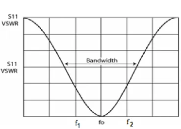
The bandwidth of an antenna means the range of frequencies that the antenna can operate. The bandwidth of an antenna is defined as the range of frequencies within which the performance of the antenna, with respect to some characteristics, conforms to a specified standard (James, J.R., and P.S. Hall(Eds), 1989). In other words, there is no unique characterization of the bandwidth and the specifications are set to meet the needs of each particular application. There are different definitions for antenna bandwidth standard.
Return loss is a measure of reflection from an antenna. 0 dB means that all the power is reflected; hence the matching is not good. -10 dB means that 10% of incident power is reflected; meaning 90% of the power is accepted by the antenna. So, having -10 dB as a bandwidth reference is an assumption that 10% the energy loss. Referring to Figure 3.9, the value of bandwidth can be calculated in the form of percentage as formula (3.7) below;
(3.7)
21
3.3 Microstrip Patch Antenna Feed Techniques
This section includes the most used feed techniques. In general, whatever the feeding technique name, main objective is to ensure compliance with the impedance. achieve harmony to impedance guarantees to pass to metallic patch a huge portion of the transmitted power from supply. On the other hand, a feeding technique for an antenna compatibility is very important also it is to focus on. Feeding methods are listed below;
3.3.1 Probe Feed
Probe feed technique is created by a probe is soldering through to the dielectric layer from metallic patch as shown in Figure 3.10. The probe can be any conductor or coaxial cable. Probe should be placed in the coordinate where provided the best impedance harmony.
Figure 3.10 A coaxial feeding view
There are also some limitations in this method:
Because of solder and the conductor pass through the surfaces, radiation efficiency become lower why fringing on surface current. Requires use of many solder in array antenna is not good farmland. For thick dielectric layer antennas, the probe cable requires long, it
22
3.3.2 Microstrip Feed
In microstrip feed, power is transferred metallic with the help of a thin conductive which is illustrated in Figure 3.11. The main advantage of the technique, feeding the same item from the metallic patch in case of a planar structure formation. This condition is a surface wave-reducing situation. It can be easily adapted to the antenna. Metallic patch is a continuation of the feed strip. However as the thickness of the dielectric substrate being used, increases, surface waves and specious feed radiation also increases, which bassinet the bandwidth of the antenna. The feed radiation also leads to undesired cross polarized radiation.
Figure 3.11 A microstrip feeding view
Microstrip line feed is one of the easier methods to fabricate as it is a just conducting strip connecting to the patch and therefore can be consider as extension of patch. It is simple to model and easy to match by controlling the inset position. However the disadvantage of this method is that as substrate thickness increases, surface wave and spurious feed radiation increases which limit the bandwidth.
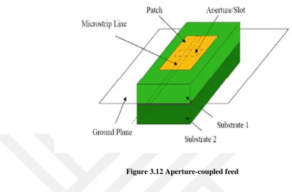
3.3.3 Aperture Coupled Feed
In this feeding technique, the feeding system is separated by a second place from the metallic patch (Figure 3.12). Coupling between the patch and the feed line is made through a slot or an aperture in the ground plane. The aperture coupled feed eliminates feed-line radiation and also allows thick substrate as a probe reactance which is not an issue (M. Ramesh and Y. Kb, 2003).
23
Figure 3.12 Aperture-coupled feed
The coupling aperture is typically focused descender part of the patch, main to decrease cross-polarization due to symmetry of the configuration. The amount of coupling from the feed line to the patch is decided by using the shape, length, dimensions and place of the aperture, for the reason that floor plane separates the patch and the feed line, spurious radiation is minimized. Generally, a high dielectric material is used for bottom substrate and a thick, low dielectric constant material is used for the top substrate to optimize radiation from the patch (S K Behera, 2008).
24
4 THE EFFECTS OF ANTENNA PROPERTIES ON THE READ DISTANCE
In passive backscatter RFID structures, the operational energy required by means of the tag is transmitted from the reader. This calls interest to the full overall performance of the radio link among the reader and the tag. The properties of the reader or the tag, including transmitting electricity, antenna benefit, running frequency, radar pass-segment, nice factor, powerful aperture or scatter aperture, polarization, and receiver sensitivity, are considered as a few primary elements affecting reading distance.
4.1 The Effect of Antenna Gain
Antenna gain affects the read distance of the passive backscatter RFID system, in which the reflection of electromagnetic waves from the object is used for data transmission from the tag to the reader. According to Friis transmission equations in free space, the read distance R is proportional by formula as;
√ (4.1)
where the is the wavelength, is the power transmitted by the reader, is the gain of the transmitting antenna, is the gain of receiving tag antenna, is the receiving power of the reader antenna, and K is system (modulation) loss. Equation (4.1) demonstrates that both reader antenna gain and tag antenna gain affect the read distance of the passive backscatter RFID system. Furthermore, contrast to tag antenna gain, reader antenna gain affects read distance remarkably.
4.2 The Effect of Antenna Frequency
The operating frequency ranges for common passive backscatter RFID systems are 868 MHz, 915 MHz, 2.45 GHz, and 5.8 GHz. Correspondingly, wavelengths for these frequencies are 0.3456 m, 0.3279 m, 0.1224 m, and 0.0517 m. According to equation (4.1), the read distance is directly proportional to the wavelength used. Via the usage of a lower frequency, i.e. an extended wavelength, the read distance can be expanded. In some instances the RF signal from the reader to the tag has to propagate
25
thru an absorbing material. Thus, the frequency used has an effect on the propagation losses in the material. Since antenna dimensions are proportional to the wavelength used, a lower frequency and a longer wavelength mean a larger tag size. In most cases, the antenna size is a proscribing factor inside the miniaturizing of passive RFID device tags. normally, folded dipole antennae and microstrip patch antenna are used as tag antenna.
4.3 The Effect of Antenna Polarization
The polarization inequality between the transmitting antenna and receiving antenna can be termed the polarization mismatch. The amount of power extracted by the antenna from the incoming signal will not be a maximum on account of the polarization loss (C.A.Balanis, 1997). Thus, antenna polarization mismatch affects the read distance of the passive Backscatter RFID system. Assuming that the electric field of transmitting antenna or incoming wave can be expressed as
̂
̂
(4.2)
where ̂ wave is the unit vector of the wave, and the polarization of the electric
field polarization of receiving antenna can be expressed as
̂
̂
(4.3)
where ̂ is its polarization vector, and the polarization loss can be taken intoaccount by introducing a polarization loss factor. The polarization loss factor (PLF) is defined as
| ̂
̂ | | | (4.4)
where is the angle between the ̂ and the ̂ . Typically, the polarization loss issue PLF is expressed in decibels. From (4.4), it's far regarded that the electricity loss starts to increase notably with the attitude of polarization mismatch growing. In some cases, the use of circularly polarized antennae on the reader improves the RFID system performance. In those cases, the effect of polarization mismatch can be neglected and angle between the reader antenna and the tag antenna has no effect on
26
the read distance. However, if the tag antenna is linearly polarized, but the reader antenna is circularly polarized, there is a 3 dB power loss, irrespective of the angle between the antenna, compared to the case in which the polarization matched, linearly polarized antenna are used on both the reader and the tag.
Circular polarization enables to acquire or transmit through antennas without considerably converting the output voltage. In lots of applications, these antennas running at low power density, whilst the transmitting power is low and the transmission distance is long. The circular polarization (CP) is the combination of nonorthogonal modes independently excited by way of an willing slot and open termination at the stop of the CPW line. Because of this, the proposed antenna can generate a linear polarization in any direction and also allow a symmetrical radiation sample.
UHF RFID device usually undertake linearly polarised antennas as tag antennas because of their low fee and easy fabrication. but, most RFID systems are used to hit upon cell objects, for instance, in RFID utility of deliver chains, the shipment on that is installed a tag may be transported along side a deliver chain. If the reader antenna linearly polarised, it's possible that the tag antenna and the reader antenna can be aligned orthogonally to each other. While that happens, the reader will now not be capable of read or software RFID tags. Subsequently, RFID reader antennas regularly undertake circular polarization to make certain in most of the instances the device can carry out efficiently (O. Bostan, 2014). As a result, the polarization efficiency among reader antenna in round polarisation and a tag antenna in linear polarization is 0.5 (or -3 dB).
27
5 DESIGN OF AN UHF MICROSTRIP PATCH ANTENNA
In this thesis, two different types of microstrip antennas for RFID systems have been designed in UHF band (865- 868 MHz for Europe).
5.1 UHF Antenna Design
Microstrip patch antennas in this thesis have been designed for UHF frequency specifically 868 MHz as center frequency. Microstrip patch antenna (also known as printed antennas) is a popular type of antennas. A patch antenna is a narrowband, wide-beam antenna fabricated by etching the antenna element pattern in metal trace bonded to an insulating dielectric substrate with a continuous metal layer bonded to the opposite side of the substrate which forms a groundplane as Figure 5.1. Common microstrip antenna radiator shapes are square, rectangular, circular and elliptical, but any continuous shape is possible. Some patch antennas contain a dielectric substrate and some of them suspend a metal patch in air above a ground plane using dielectric spacers; the resulting structure is less robust but provides better bandwidth.
Figure 5.1 The dimensional view of microstrip patch antenna
Microstrip antennas are also relatively inexpensive to manufacture and design because of the simple 2-dimensional physical geometry. They are usually employed at UHF because the size of the antenna is directly tied to the wavelength at the resonance frequency. A single patch antenna provides a maximum directive gain of around 5 dBi (C. A. Balanis, 1997). It is relatively easy to print an array of patches on a single (large) substrate using lithographic techniques. Patch arrays can offer several better gains than a single patch at little extra value; matching and phase adjustment
28
can be accomplished with published microstrip feed structures, once more within the equal operations that form the radiating patches. An advantage inherent to patch antennas is the ability to have polarization diversity. Patch antennas can easily be designed to have Vertical, Horizontal, Right Hand Circular (RHCP) or Left Hand Circular (LHCP) Polarizations, using multiple feed points, or a single feedpoint with asymmetric patch structures. This unique property allows patch antennas to be used in many types of communications links that may have varied requirements. Various types of antennas have been designed for ultra-high frequency (865-868 MHz for Europe) to test with respect to efficiency. A commercial RF and Microwave Design Software from AWR Corporation (Applied Wave Research) was used to design and simulate antenna projects.
First of all Eq. (5.1) is used to calculate the approximate dimensions of the antennas;
√ (5.1)
where c is the speed of light in air (3 × m/s), f is resonant frequency of antenna, is dielectric constant of substrate and is length of antenna. This formula gives the length of the antenna (patch). This is important for designing to be precise as the length affects the operating frequency of the antennas. Then, the length of ground plane is calculated. The area of the ground plane should be three times bigger than the area of the patch to radiate efficiently. After these calculations, all the parameters of dielectric material and the ground plane dimensions of the antenna are given to AWR Microwave Office. After these calculations, all the parameters of dielectric material and the ground plane dimensions of the antenna are given to AWR Microwave Office. The followings are some hints that affect the dimensions and the behavior of antenna. With the increase in substrate thickness, the fringing fields from the edges increase, which increases the extension length, there by decreasing the resonance frequency. Besides, the bandwidth of the antenna increases (Srivastava, D.K., Vishwvakarma, B.R., Saraswat, R.C., Saini, J.P, 2007). With decrease in permittivity, size of patch and bandwidth increases due to increase in fringing fields (Srivastava, D.K., Vishwvakarma, B.R., Saraswat, R.C., Saini, J.P, 2007). A higher permittivity reduces the patch size and the extent of the fringing fields. Consequently, the radiation is due to a narrow magnetic current ring around the patch periphery, which
29
normally gives asymmetric radiation patterns. A thicker substrate, on the other hand, does not reduce the patch size significantly, but extends the zone of the fringing fields, thus resulting in a broad radiation ring (James, J.R. and Hall, P.S, 1989). Fringing fields are the fields thar are responsibe for radiation as seen in Figure 5.2.
Figure 5.2 The fringing fields
5.2 Design Procedure and Steps
In general, patch antennas have the length of half-wave structures at the operation frequency of fundamental resonant mode. Since the fringing field acts to extend the effective length of patch, the length of the half-wave patch is slightly less than a halfwavelength in the dielectric substrate material. Approximate value for the length of a resonant half-wavelength path is given by Eq. (5.1). Then, all other the dimensions of the patch antenna are calculated based on equations (5.2) and (5.3). The width is given by
√
(5.2)
where is the resonant frequency of the patch antenna. The effective dielectric constant for the case of (W/h > 1) is given by Eq. (5.3);
√
(5.3)30
√
(5.4)
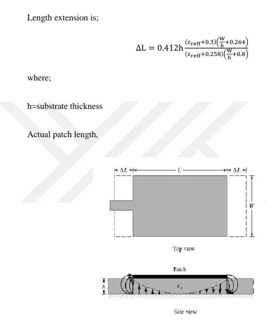
Length extension is;
( )( )
( )( )
(5.5)
where;
h=substrate thickness
Actual patch length,
Figure 5.3 Physical and effective length of microstrip antenna (Balanis, 2005)
(5.6)
The resonant frequency,
( )√
31 with c is the speed of light.
Microstrip feed line use for patch antenna determine to be fed for 50 ohm for line impedance (Zo) is calculated by;
√
[
] (5.10)
where; h=substrate thickness Zo=line impedanceThe feed point must be located at that point on the patch, where the input impedance is 50 ohms for the resonant frequency. Hence, a trial and error method is used to locate the feed point. In this case we use PSO to obtain the optimum feed depth, where the return loss (RL) is most negative (i.e. the least value). According to (Hasse R., Demir V., Hunsicker W., Kajfez D. ve Elsherbeni A., 2008) there exists a point along the length of the patch which gives the minimum return loss.
( ) ( ) ( ) (5.12) where, ( ) ( ) (5.13)
{
√*
+
√ [ * +]} (5.14)
where,32 { ( ) ( ) (5.15) and, ∫ [ ( ) ] ( ) (5.16)
33
6 DESIGN AND SIMULATION OF RFID READER ANTENNAS 6.1 The Proposed UHF RFID Antennas Structure
In this thesis, firstly, the used dielectric substrate is selected by taking into consideration the gain, efficiency, good radiation pattern and so on. The antennas are designed by using Roger RO4003C which is one of the products of Rogers Corporation as dielectric material (Rogers Corporation, 2016). Its product features are; dielectric constant is = 3.55 and tangent loss is tan δ = 0.027, thickness is h = 1.524 mm. The reasons of this substrate selection are low-loss property, plenty plates of availability in Yasar University Antennas and Microwave Laboratory and easy manufacturing.
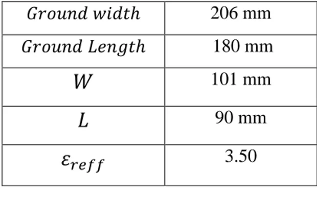
Most RFID antenna labels on the market are linearly polarized, at the same time, many RFID reader structures use circular polarized antennas to make certain that tags can be examine in any orientation. Those antennas are frequently targeted via their circular advantage and axial ratio. Because tag variety strongly depends on antenna advantage, it is crucial to recognize the courting among the linear advantage of an antenna and its circular advantage. For the proper functioning of the standard microstrip antenna, the ground plane which is located on the back side of the antenna is recommended to be at least twice the size of the microstrip patch antenna. By using the formulations in Chapter 5, the dimensions of a standard patch antenna at 868 MHz center design frequency is calculated for RO4003C substrate. A simulation view of traditional microstrip patch antennas fed by a microstrip line with a 100 Ω quarter-wavelength transformer matching network is depicted in Figure 6.1 where the dimensions are also given in Table 6.1.
Table 6.1 The parameters of the designed microstrip patch antenna without segmented loop
206 mm
180 mm
101 mm 90 mm
34
Figure 6.1 CST model of a traditional rectangular patch on Roger RO4003C at 868 MHz
The reflection coefficient (S11 values) for the traditional antenna given in Figure
6.1 is shown in Figure 6.2. The resonance frequency is found to be 868.9 MHz with S11 value lower than -10 dB, which is so close to the desired center frequency of 868
MHz. So, the equations given in Chapter 5 are verified with this simulation result.
Figure 6.2 The reflection coefficient (S11 parameter) of the traditional antenna in Figure 6.1.
The ground plane of above antenna is found as an area of approximately 206 mm x 180 mm as shown in Figure 6.1. This simulation was made just for
35
understanding of the before and after the optimization was made to better understand. This ground plane area is evaluated to be too large; thus, another antenna structure which is more compact than the traditional one is considered. Due to the ground is too large, and a compact structer is requested. One of the objectives of this thesis is to reduce the area of the total antenna, segmented loops makes us to achieve a smaller structure.
For this purpose, a designed antenna structure (linearly polarized version) as shown in Figure 6.3 is proposed. In linear polarization design, substrate dielectric constant has been taken as 3.55 which is given as the suggested value for the applications in specification datasheet of RO4003C. The structure consists of of broken loop (parasitic elements) on the both side of the antenna, and by this way it is obtained much more smaller ground plane size and in total, a compact antenna. The paramatization and optimization tools in CST Microwave Studio provide that shows effect of the properties changing, find the parameter which maximize or minimize a given effect or fulfill a certain goal. This tool can optimize any property of the model that can be parameterized, such as the dimensions or positions of a component or the materials properties. The results of the formula predicted but then downsized the antenna structure which is presented as shown in Figure 6.3. Placement of the patch antenna inside the segmented loop is chosen to achieve as compact antenna structure as possible, although this approach has a tradeoff in blocking part of the magnetic flux through the loop (Bijaya Shrestha, Atef Elsherbeni, 2011). The initial dimensions of the antennas are obtain by utilizing the equations in Chapter 5, and the corresponding values are given in Table 6.2. Afterwards, by benefiting from the study of (Bijaya Shrestha, Atef Elsherbeni, 2011) and using CST Microwave Studio 2015, the final design for the linearly polarized version is achieved where the corresponding final dimensions are given in Figure 6.3 and Table 6.2 in detail. Table 6.1 and Table 6.2 show the differences in dimensions such that total ground area of the traditional patch antenna is 206 mm × 180 mm = 3.70 cm2 whereas total ground area of the proposed microstrip patch antenna is 148 mm × 139 mm = 2.06 cm2. Therefore, the proposed linearly polarized antenna makes about %55.6 reduction in the total area of the antenna as compared to the traditional microstrip patch antenna.
36 (a)
(b)
Figure 6.3 (a) Designed linearly polarized patch antenna from top view (b) linearly polarized patch antenna bottom view in CST Microwave Studio
37
Table 6.2 The initial parameters of the designed microstrip patch antenna
148 mm 139 mm 101 mm 90 mm 3.50 91 mm
0.63 mm
As the second design, a circularly polarized version is considered. The circular polarization modulation is always used in the RFID system. Its basic feature is that logical zero is transmitted as the left hand circulary polarized (LHCP) wave, and a logical one is represented by right hand circulary polarized (RHCP) wave (W. L. Stutzman and G. A. Thiele, 2000). CP antennas can be realized when two orthogonal modes of equal amplitude are excited with a phase difference. For creating circular polarization antenna, a corner truncated square patch is used to replace the normal square patch, which will improve the circular polarization performance of the antenna and its port characteristics. Axial ratio is a parameter that is important for antenna design which is circulary polarized. it is obvious that segment variations between the excitation signals purpose adjustments inside the axial ratio. these factors degrade the sign even supposing a perfect CP sign (axial ratio=0 dB) has been transmitted and the obtained CP signal exhibits statistical steady with its axial ratio.
The truncated part of the patch is calculated below equations;
√
(6.1)