ISCAS 2000 - IEEE International Symposium on Circuits and Systems, May 28-31, 2000, Geneva, Switzerland
A SYNTHESIS TOOL FOR THE MULTIPLIERLESS REALIZATION OF FIR-
BASED MULTIRATE DSP SYSTEMS
Arda Yurdakul
Kadir Has University
Electronics Engineering Department
Vefa Bey Sok,
No:5
Gayrettepe,
808 15
Istanbul,
TURKEY
ABSTRACT
In this study, a synthesis tool using a novel multirate folding technique, which handles each FIR filter in a multirate DSP system as n single node, is developed. A new architecture is presented for the multiplierless realization of a fold of multirate FIR filters. This synthesizer fully exploits the redundancies (i.e. "idle" and "missing" cycles) and common terms in multirate systems without sacrificing from overall system quality to produce multiplierless multirate systems. I t also enables the usage of a single clock for all parts of the circuit.
1.
INTRODUCTION
Hardware implementation of multirate systems has been a great interest in last decades. Even though multirate techniques are used to gain from computational complexity [I], it requires multiple clocks yielding clock synchronization problems.
In multirate techniques, signals are decomposed to be worked on separately. As a result, multirate systems incorporate several filters, usually, of similar structures. For hardware people, FIR filters are the most selected ones because of their stability, linear phase, easy design and cascadibility, comparable efficiency to that of an IIR filter by increasing the number of cascades, low sensitivity to quantization of tap coefficients [2].
To date, there is a single synthesizer generating multirate DSP architectures by Denk and Parhi [3]. It uses multirate folding to fully utilize the idle units, hence realizes the whole system using a single clock. The multirate folding is used for simple arithmetic, logic and delay operations in a data-flow-graph in that tool. As a result, any multirate system can be realized using it. However, it is too generic in most of the hardware realizations of multirate DSP systems to produce .compact layouts, because most of the applications like wavelet and block transform use similar blocks even in their algorithmic representations. Usually the filters in a multirate system are formed using a set of coefficients like Alkin's coefficient set for M-band block transforms [4]. Therefore, a multirate transform can be realized using a single coefficient set for all filters in a fold instead of using a dedicated coefficient set for each filter in a fold. The synthesizer proposed by Denk and Parhi is incapable of exploiting this feature of filter-based multirate systems.
The tool proposed in this paper exploits this feature of multirate DSP systems for their hardware realization. It is capable of
handling each FIR filter in a multirate system as a single node. Therefore, similar filters in the system can be folded on to a single filter provided that they satisfy the multirate folding criteria. Also,
the new tool takes care of the fact that the filters in a multirate system are formed using a set of coefficients. This fact gives the designer a freedom to fold FIR filters with the same tap-length but different coefficients on to a single filter architecture, which realizes tap multiplications without multipliers. Multiplierless realization of single-rate FIR filters is a well-studied subject [ 5 ] - [SI. The novelty of our study comes from the multiplierless realization of multirate FIR filters in a fold. I t is known that the speed of each pipeline stage in a fold has to be identical and it is hard to guarantee this in MCMhbexpression sharing optimization. However, this new tool guarantees identicalness of stages such that each operator in the system (i.e., adders for the multiplierless systems) can have plenty of pipeline stages provided that operation at each stage is completed in one clock cycle. Hence, an output production rate at clock frequency is guaranteed. The resulting circuit layouts are both compact, efficient with maximum throughput and fully synchronized in the whole circuit by using a single clock.
In the next section, the multiplierless architecture for a fold of multirate FIR filters will be explained. Following it, Section 3, will mention about folding criteria for multirate nodes. Section 4 will focus on the scheduling algorithm. Section 5 will be used for the
demonstration of the experimental results and conclude the work.
2.
MULTIPLIERLESS ARCHITECTURE
FOR FOLDING MULTIRATE FIR FILTERS
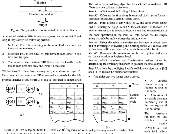
The quantized tap coefficients of all FIR filters in a fold are exposed to a common subexpression elimination procedure altogether as explained in [9]. Therefore, a set of adders, Scaling Adders block in Figure 1, is used to carry out basic multiplications. The results are stored in Registers block to be organized by the Inverting/ Noninverting and Shifting block that either negates or shifts or keeps the data to produce the real tap multiplications. The output of the Inverting/Noninverting and Shifting block is used by Combination Adders block, which is used to generate the final multirate FIR filter outputs in the user-determined fold. Remember that an FIR filter has a single input and a single output. However, our architecture is designed to produce parallel outputs that are necessary to handle interpolation processes efficiently.3.
FOLDING OF MULTIRATE NODES
A multirate system consists of nodes at different rates. The operation rate of each node n in the system, pn, must be determined before folding is applied:
0-7803-5482-6/99/$10.00 02000 IEEE
In the above equation, pn is the operation rate of the n'th ancestor node of n, pd is the period of the decimating commutator (i.e. data at the output of the ancestor node a is mixed at the input of node n at a rate of pd), pi is the period of the interpolating commutator (i.e. data at the output of the ancestor node n is sampled at the input of node n at a rate of pi), N and M are the decimation and interpolation factors as shown in Figure 2(a). If there exists no decimating and interpolating commutators, their period is, of course, I . It should be noted that p n must be a unique number to prevent data loss.
, input Adders Inverting/Noninverting and Shifting
I
Combination Adders-U-
outputFigure I Target architecture for a fold of multirate filters A group of multirate FIR filters in a system can be folded if and only if they satisfy the following criteria:
Multirate FIR filters existing in the same fold must have an
the realization of the second criterion for a fold of 4-tap multirate FIR filters. The third criterion can be illustrated by concentraling on Figure 2(b). If nl and n2 share the same ancestor of rate I both of them can exist in the same fold. However, if they share different sources of rate I , folding shown in Figure 2(b) will be impossible because one of the nodes will not be able to get data from its input. There is a single criterion for all other simple nodes such that there exists a single ancestor at each input of the node under study at a clock instance. This is necessary to avoid bus conflict.
4.
THE SCHEDULING ALGORITHM
After checking the validity of the folds in the multirate system, the system must be scheduled. The scheduling is handled by two main subscheduling algorithms by this new synthesizer: (A)Scheduling of multirate filters, (B)Scheduling of other nodes to complete the scheduling.
4.1
Scheduling of Multirate FIR Filters.
The outline of scheduling algorithm for each fold of multirate FIR filters can be explained as follows:
Step A l . ASAP schedule Scaling Adders block.
Srep A2. Calculate the time delay in terms of clock cycles for each seed multiplication at Scaling Adders block.
Step A3. Form a table of tap width, i.e. K, and clock cycles length and fill it using pn, pd, pi, N a n d M for each node n in the fold in a similar manner that is shown in Figure 2 and find the periodicity of the node operations in the fold, i.e. fold period, TF, by simply going through the table columnwise and rowwise.
StepA4. Using the table, determine the instance at which each unit at InvertinglNoninverting and Shifting block will receive data identical tap number, K .
Multirate FIR filters have to complement each other in the time and tap span
so that there will be no bus conflict at the input of this block. SfePA5. Determine the minimum "2Jer of registers and CanY out data allocation in Registers block.
Step A6. ASAP schedule the Combination Adders block by Step A5 is done by modifying Parhi's well-known algorithm, [IO] and [ i l l to reduce the number of registers:
The inputs to the must be such determining the switching instances to produce the final outputs, that at each time slot only one input is processed.
We can illustrate these criteria using the system shown in Figure 2. Here there are two multirate FIR nodes and nl,j stands for the i'th
process instance of nl. Figure 2(b) and (c) are used to demonstrate A variable
Variables can live longer than a period,
Taps
System clock cycle1
(b) (c)Figure 2 (a) Two K-tap multirate FIR filters and the organization of output processing at each tap when K=4 and (b) M = l , N=2 (c) M=2, N = l . Both of these tables are periodic by 2 clock cycles, i.e: q = 2 .
cannot occupy a register as soon as it is born.
Allocation of a variable does not necessarily end qt the last register if it is not dead. The worst-case run-time of this scheduler is mainly O(NF+TF+VF:I for each fold, where
NF is the sum of adders in the Scaling Adders and Combination Adders blocks, V F is the number of variables obtained from Step
A4 to determine the register number and data allocation on those registers. Note that scheduling of a multirate FIR filter that do not exist in a fold can be done by using the same algorithm.
.... ~ ...
(a> (b)
Figure 3 Four-band block transform (a) analysis, (b) synthesis.
4.2
Scheduling
of
Other Nodes
Since multirate FIR nodes are scheduled using tables, other nodes are also scheduled using tables to preserve connectivity of the system. The outline of this algorithm is presented as follows: Step B I . For each node or fold in the system form a table of number of inputs width and clock cycles length. This table is the degenerate form of the table shown in
Figure 2. Fill it similarly.
Step B2. Using the data in all tables in the system, including the ones for multirate FIR nodes, either folded or not, make cross-table search by first finding the periodicity of the operations between nodes and folds, i.e. internode period,q.
Step B3. Determine the minimum
number of registers and carry out the data allocation.
The worst case run-time of this scheduler is mainIy’O(q+vl) for each edge between an ancestor and the node in the system, where q ’ i s the number of variables obtained from Step B3 to determine the register
number and data allocation on those registers.
If there exists p number of multirate FIR filters folds or nodes and q number of edges, then the overall run-time of the scheduler is O @ ( N F + ~ F + V F ) + ~ ~ ( ~ + V I ) ) .
5.
EXPERIMENTS AND CONCLUSION
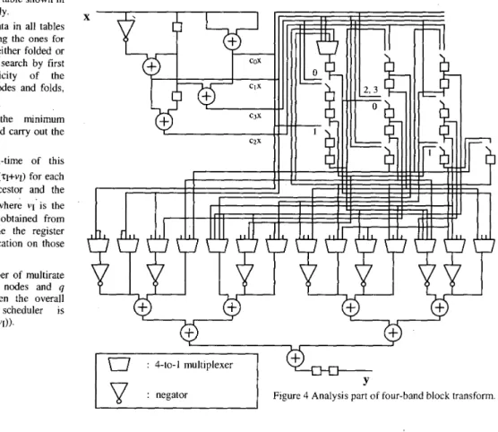
The algorithm is used to realize the analysis and synthesis parts four-band block transform of Figure 3 with eight-bit quantized coefficient sets as given in [9] by folding 8-tap G filters of each part separately as indicated by dotted rounded rectangles in the same figure. The resulting circuit layouts are shown in Figure 4 and Figure 5. The adders and negators in the realized system have unit
operation delays, i.e. delay of each operator is one clock cycle. The whole system is realized using only (2+16+2)+(2+20)=42 delay elements. The original system would require 2(4~7)+3=59 registers. Also a minimum system incorporating multipliers for FIR filters would require at least 4+4=8 multipliers [3], but our system requires 4+4=8 adders for tap multiplications. Note that adders always cover smaller area than multipliers! The layouts are prepared without using subtractors that can also be used as well. Note that he system uses single clock for both analysis and synthesis parts.
In this study, a new synthesis tool is developed for the multiplierless hardware realization of FIR-based multirate DSP algorithms using multirate folding. It allows usage of operators, which can have plenty of pipeline stages provided that operation at each stage is completed in one clock cycle. The generated systems in the examples prove that compact architectures using a single clock can be realized if the folding sets are formed correctly.
: 4-to-1 multiplexer
I
L
I
H
: negatorY
Figure 4 Analysis part of four-band block transform.
I
6.
REFERENCES
[I] N. J. Fliege, Multirate Digital Signal Processing, John Wiley & Sons Inc., Chichester, England, 1994.
[2] R. E. Crochiere and L. R. Rabiner, Multirare Digital Signal Processing, Prentice Hall Inc., New Jersey, USA, 1983. [3] T. Denk and K. K. Parhi, “Synthesis of folded pipelined
architectures for multirate DSP algorithms,” IEEE Trans. on VLSI Systems, vol 6, pp. 595-607, Dec. 1998.
[4] 0. Alkin and H. Caglar, “Design of efficient M-band coders with linear phase and perfect reconstruction properties,” IEEE
Trans. On Acoust. Speech and Signal Proc., vol. 43, pp. [5] A. G. Dempster and M. D. Macleod, “Use of minimum adder multiplierless blocks in FIR digital filters,” IEEE Trans. on CAS-I/, vol42, pp. 569-577, Sept. 1995.
[6] R. 1. Hartley, “Subexpression sharing in filters using CSD multipliers,” IEEE Trans. on CAS-11, vol 43, pp. 677-688, Oct
1995.
1579-1590, July 1995.
Y
[7] M. Potkonjak, M. B. Srivastava and A . P. Chandrakasan, “MCM: Efficient and versatile framework and algorithms exploring CSE,” IEEE Trans. on CAD, vol 15, pp. 151-165, Feb. 1996.
[8] R. Pasko, et. al., “A new algorithm for CSE,” /EEE Trans. on CAD, vol 18, pp. 58-68, Jan. 1999.
[9] A. Yurdakul and G. Diindar, “Multiplierless realization of linear DSP transforms using common two-term expressions,”
Journal of VLSI Signal Processing, v01.22, pp. 163-172, Sept. 1999.
[lo] K. K. Parhi, “Calculation of minimum number of registers in arbitrary lifetime chart,” 1EEE Trans. on CAS-11, vol 41. pp. 434-436, June 1994.
[ I 11 K. K. Parhi, “Systematic synthesis of DSP data format converters using lifetime analysis and forward-backward register allocation,” IEEE Trans. on CAS-I/, vol 41, pp. 434- 436, June 1994.
: 4-to-I multiplexer
Figure 5 Synthesis part of four-band block transform