I
NTRODUCTION
The abundance of water on Earth distinguishes our “Blue Planet” from others in the solar system. Nearly 71 percent of the Earth’s surface is covered with water, 97 percent of it being sea water. This vast underwater world is extremely rich in natural resources such as valuable minerals and oil fields waiting to be explored. Underwater exploration activities are mainly hampered by the lack of effi-cient means of real-time communication below water. Although wireline systems through deploy-ment of fiber optical links have been used to pro-vide real-time communication in some underwater applications, their high cost and operational disad-vantages become restrictive in many cases. Wire-less communication is a promising alternative and an ideal transmission solution for a wide range of underwater applications including offshore oil field exploration/monitoring, oceanographic data collection, maritime archaeology, environmental monitoring, disaster prevention, and port security, among many others.
Wireless transmission of information under water can be achieved through radio, optical, or sound waves. Due to the high attenuation of radio frequency (RF) signals in water, long-range RF
communication is problematic and requires the use of extra low frequencies, which necessitate large antennas and high transmit powers. Although early military use of underwater RF communications is known, the first commercial underwater RF modem was introduced only a few years ago.1 However, their short transmission range (1–100 m) makes this option unappealing for most practical purposes. Optical waves do not suffer much atten-uation, but are severely affected by absorption, scattering, and high levels of ambient light limiting the transmission ranges. Among the alternatives for wireless communications, acoustic transmission is the most practical and commonly employed method due to favorable propagation characteris-tics of sound waves under water.
As diverse and data-heavy underwater appli-cations emerge, demanding requirements are further imposed on underwater acoustic commu-nication (UWAC) systems. Future UWAC net-works might consist of both mobile and stationary nodes that exchange data such as con-trol, telemetry, speech, and video signals among themselves as well as a central node located on a ship or onshore. The submerged nodes (which can, e.g., take the form of an autonomous under-water vehicle/robot or diver) can be equipped with various sensors, sonars, video cameras, or other types of data acquisition instruments. Innovative physical layer (PHY) solutions are therefore required to develop efficient, reliable, and high-speed transmission solutions tailored to the challenging and diverse requirements of underwater applications. This tutorial article first provides a contemporary overview of UWAC and presents a summary of underwater channel characteristics. Then it investigates cooperative (i.e., relay-assisted) transmission as a powerful PHY solution in the context of UWAC consider-ing the inherent characteristics unique to under-water acoustic channels.
The rest of the article is organized as follows. First, we present a literature overview of UWAC. Next, we provide a summary of the underwater channel characteristics, including path loss, fad-ing, and ambient noise, that need to be consid-ered in system design and analysis. We then introduce the multicarrier cooperative system
A
BSTRACT
This article presents a contemporary overview of underwater acoustic communication (UWAC) and investigates physical layer aspects on coop-erative transmission techniques for future UWAC systems. Taking advantage of the broad-cast nature of wireless transmission, cooperative communication realizes spatial diversity advan-tages in a distributed manner. The current litera-ture on cooperative communication focuses on terrestrial wireless systems at radio frequencies with sporadic results on cooperative UWAC. In this article, we summarize initial results on coop-erative UWAC and investigate the performance of a multicarrier cooperative UWAC considering the inherent unique characteristics of the under-water channel. Our simulation results demon-strate the superiority of cooperative UWAC systems over their point-to-point counterparts.
ACCEPTED FROM
OPEN
CALL
Suhail Al-Dharrab, University of Waterloo
Murat Uysal, Özyeg
˘in University
Tolga M. Duman, Bilkent University
Cooperative Underwater Acoustic
Communications
This work is supported by Qatar National Research Fund (QNRF) grant through National Priority Research Program (NPRP) No. 09-242-2-099. 1http://www.wfsdefense. com/index.php/about_wfs _defense/
model under consideration. We provide the out-age performance of the cooperative UWAC sys-tem and compare its performance to conventional point-to-point transmission under the assumptions of various channel and system parameters. Finally, we provide concluding remarks and some future research directions.
L
ITERATURE
O
VERVIEW OF
UWAC
E
ARLYY
EARS: A
NALOGM
ODULATION ANDN
ON-C
OHERENTD
IGITALC
OMMUNICATIONSStarting in World War I, research efforts first focused on the design of sonars to detect obsta-cles for navigation and targets. The development of UWAC was later, during World War II, when the U.S. Navy deployed underwater telephones for communication with submarines. This first underwater acoustic telephone operated at 8.3 kHz and used single-sideband suppressed carrier (SSB-SC) amplitude modulation. Until the 1980s, research efforts on UWAC were mainly dominated by military applications. In later years, following the advances of digital signal processing (DSP) and very large-scale integrated (VLSI) technologies, new generations of digital UWAC systems were introduced targeting a variety of applications for the civilian market [1]. In the 1980s, it was commonly believed that the time variability and dispersive multipath propagation characteristics of the ocean would not allow the use of phase-coherent modulation techniques such as phase shift keying (PSK) and quadrature amplitude modulation (QAM). The prevailing design choice for modulation in acous-tic modems at the time was frequency shift key-ing (FSK). It is well known that FSK suffers from bandwidth inefficiency. Coupled with the limited bandwidth availability of the underwater channel, FSK became a bottleneck, limiting the operation of UWAC systems to very low rates unacceptable for many modern applications.
1990
S–2000
S: T
RANSITION INTOP
HASE-C
OHERENTS
YSTEMSIn the 1990s, with increasing demands for higher data rates, the research focus shifted toward design of coherent acoustic modems. One approach toward this purpose was to employ dif-ferentially coherent detection to ease the prob-lematic carrier recovery in underwater acoustic channels. However, differential techniques inevitably result in performance degradation with respect to coherent detection. In [1], Stojanovic
et al. adopted “purely” phase-coherent detection
and designed a receiver built on adaptive joint carrier synchronization and equalization. The maximum likelihood (ML) algorithm for such a joint estimator suffers from excessive complexity, particularly for the underwater channel charac-terized by long channel impulses. Therefore, as a low-complexity solution, the receiver algorithm in [1] adopts a decision feedback equalizer (DFE), the taps of which are adaptively adjusted using a combination of a recursive least squares (RLS) algorithm and a second-order phase locked loop (PLL). Since the seminal work of Stojanovic et al. in [1], there has been a growing interest in
phase-coherent UWA communication systems. Much research effort has particularly focused on the design of low-complexity equalization schemes, which is a key issue for underwater channels with large delay spreads. Particularly, sparse channel estimation/equalization and turbo equalization have been investigated by several research groups [2, references therein].
C
URRENTS
TATE AND THEF
UTUREEmerging data-heavy underwater applications impose further requirements on UWAC system design. To address such challenges, recent advances in terrestrial wireless RF systems have been further exploited in the context of UWAC. One of the research breakthroughs in the last decade is multiple-input multiple-output (MIMO) RF communications. MIMO systems involve the deployment of multiple antennas at the transmitter and/or receiver side, and achieve significant improvements in transmission reliabil-ity and throughput. For example, in [3], Roy et
al. have investigated the application of
space-time trellis codes and layered space-space-time codes in UWAC systems. Through simulations and real-life experiments, they have demonstrated significant improvements over conventional sin-gle-input single-output (SISO) systems in terms of data rates and reliability.
Although MIMO systems successfully exploit the spatial dimension, their practical implementa-tion over frequency-selective channels (as encoun-tered in underwater channels) is challenging considering the potential high complexity of spa-tio-temporal equalizers. This has further sparked interest in research on the combination of MIMO and orthogonal frequency-division multiplexing (OFDM) for the underwater channel that has been investigated extensively in recent literature [4, references therein]. Multicarrier communica-tions implemented through OFDM is particularly attractive for underwater channels due to the fact that, with the use of a cyclic prefix longer than the multipath spread of the channel, the intersymbol interference is completely removed. Therefore, channel distortion can be compensated at the receiver on a subcarrier-by-subcarrier basis, elimi-nating the need for complex time-domain equaliz-ers. For time-invariant channels, orthogonality between the subcarriers in a multicarrier OFDM system is maintained, which simplifies the trans-mission. However, for time-varying channels, the benefits come at a cost. Particularly, for time-varying channels with high Doppler values, multi-carrier system implementation requires the deployment of judiciously designed intercarrier interference management techniques [5].
Another promising approach in the design of future UWAC systems is the potential deploy-ment of cooperative communication techniques. The basic ideas behind cooperative transmission can be traced back to Cover and El Gamal’s work on the information theoretic properties of the relay channel in 1979. The recent surge of interest in cooperative communication, however, was subsequent to the publications of Sendonaris
et al.’s and Laneman et al.’s in 2003–2004.
Coop-erative communication (also known as user cooperation or cooperative diversity) exploits the broadcast nature of wireless transmission and
Emerging data-heavy underwater applications impose further requirements on UWAC system design. To address such challenges, recent advances in terrestrial wireless RF systems have been further
exploit-ed in the context of UWAC.
relies on the cooperation of users relaying each other’s information. When a source node trans-mits its signal, this is received by the destination node and also overheard by other nodes in the vicinity. If these nodes are willing to share their resources, they can forward the overheard infor-mation to the destination as a second replica of the original signal and act as “relays” for the source node, extracting a diversity order on the number of relays. For scenarios in which there is no direct transmission between the source and destination, multihop communication can be used. This does not bring diversity gain, but the deployment of relays enables extension coverage. A rich literature already exists on cooperative communication for terrestrial wireless RF sys-tems, for example, recently published books such as Cooperative Communications and Networking by Liu et al., Cooperative Communications:
Hard-ware, Channel and PHY by Dohler and Li, Coop-erative Communications for Improved Wireless Network Transmission by Uysal, and the
refer-ences therein. However, there are only sporadic results reported for UWA applications. In [6], Carbonelli et al. have considered a decode-and-forward relaying scheme and, through an error propagation analysis, shown that this multihop communication scheme is superior to direct transmission due to the fact that the channel attenuation is much better addressed with the use of relays. In [7], Vajapeyam et al. have pro-posed a time-reversal distributed space-time block coding scheme for UWAC with the use of intermediate relay nodes implementing amplify-and-forward type protocols. They report perfor-mance improvements with their proposed scheme over single-hop UWAC systems via sim-ulations and experimental results.
In [8], Zhang et al. investigated a decode-and-forward type protocol with spatial reuse and peri-odic transmit/receive schedules for linear multihop UWAC networks. They considered the frequency-dependent signal attenuation, interhop interference, half-duplex constraint, and large propagation delays in their analysis. They demon-strated improved performance in multihop UWAC networks. In [9], Cao et al. investigated the channel capacity of relay-assisted UWAC and
discussed time synchronization issues. They fur-ther looked into the effects of source to destina-tion distance, transmit power allocadestina-tion, and relay location on channel capacity for relay-assisted UWAC systems. They observed a capacity increase in relay-assisted UWAC systems com-pared to traditional direct link communication.
Inspired by these initial results, this tutorial investigates the performance of cooperative UWAC systems, considering the inherently unique characteristics of the underwater chan-nel, and demonstrates the potential of the user cooperation concept in future UWAC networks.
U
NDERWATER
A
COUSTIC
C
HANNEL
M
ODEL
In this section, we discuss the inherent charac-teristics of the underwater acoustic channel, emphasizing the main differences and similari-ties with the well-known RF channel models.P
ATHL
OSSThe path loss in an underwater acoustic channel results from spreading and absorption losses. Let
s and a(f) denote the spreading factor and
absorption coefficient, respectively. The overall path loss2in dB is given by
LU= 10slog10dSD+ 10dSDlog10a(f) (1) where dSDis the distance between the transmit-ter and receiver. The spreading factor depends on the geometry of propagation, and a spreading factor of 1.5 is often taken as representative of practical spreading based on a partially bounded sphere. The absorption coefficient a(f) is a func-tion of frequency as well as pressure, tempera-ture, salinity, and acidity. Moreover, viscosity of pure water, relaxation of magnesium sulphate, and relaxation of boric acid mainly contribute to sound attenuation at frequencies 100 Hz–100 kHz. Several empirical formulas have been developed over the years for the characterization of the absorption coefficient including Schulkin-Marsh (1962), Thorp (1965), Mellen-Browning (1976), Fisher-Simmons (1977), and
Francois-2If the performance
esti-mate in a specific geo-graphical location is required, Bellhop software can be used assuming that one has access to some detailed information such as boundary conditions, general bathymetry, refracting sound speed profile, grazing angle, weather conditions, source angle, and receiver angle.
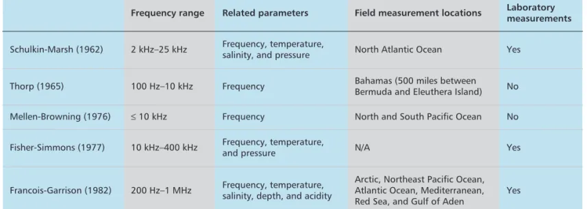
Table 1. Formulas for the calculation of sound absorption coefficient expression.
Frequency range Related parameters Field measurement locations Laboratory measurements
Schulkin-Marsh (1962) 2 kHz–25 kHz Frequency, temperature,
salinity, and pressure North Atlantic Ocean Yes
Thorp (1965) 100 Hz–10 kHz Frequency Bahamas (500 miles between
Bermuda and Eleuthera Island) No Mellen-Browning (1976) £ 10 kHz Frequency North and South Pacific Ocean No
Fisher-Simmons (1977) 10 kHz–400 kHz Frequency, temperature,
and pressure N/A Yes
Francois-Garrison (1982) 200 Hz–1 MHz Frequency, temperature, salinity, depth, and acidity
Arctic, Northeast Pacific Ocean, Atlantic Ocean, Mediterranean, Red Sea, and Gulf of Aden
Garrison (1982). A comparison of different models can be found in Table 1. Thorp’s formu-la is widely used in the literature mainly due to its simplicity. However, this formula is merely a function of frequency and ignores other parame-ters of the acoustic channel. The most compre-hensive formula for the absorption coefficient is that of Francois-Garrison’s (FG) [10] and applies for the frequency range of 200 Hz–1 MHz.
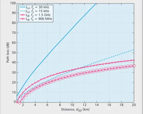
In Fig. 1, we illustrate the underwater path loss with respect to distance for operating fre-quencies of 15 and 30 kHz. We consider s = 1.5 and use the FG formula for the calculation of absorption coefficient assuming temperature of 15˚ C, depth of 50 m (i.e., shallow water), acidity of 8 pH, and salinity of 35 parts/thousand. From Fig. 1, it is observed that underwater path loss increases drastically with distance. For distances larger than 4 km, increasing the distance brings about 2.5 dB of loss per kilometer for 15 kHz. Doubling the frequency from 15 to 30 kHz will bring 17 dB of loss for a fixed distance of 4 km. To emphasize the different propagation charac-teristics of underwater acoustic and terrestrial RF wireless channels, we further illustrate the path loss for an RF channel based on the well-known Okumura-Hata model. In the calculation of terrestrial RF path loss, we consider a medi-um-small city, carrier frequencies of 900 MHz and 1.5 GHz, and assume a base station antenna height of 70 m and mobile antenna height of 1.5 m. Under these typical scenarios, it is observed that the path loss in the underwater channel is much larger than that in the RF channel and becomes a particularly limiting factor in UWAC for larger values of operating frequencies. Such large path losses provide a strong motivation for relay-assisted transmission in UWAC.
F
ADINGThe average received power is determined by the path loss, but the instantaneous level of the received power fluctuates as a result of small-scale fading effects due to multipath propagation in underwater environments. In shallow water, multipath occurs due to signal reflections from the surface, bottom, and any objects in the water. In deep water, it is primarily due to a phe-nomenon known as ray bending, that is, the ten-dency of acoustic waves to travel along the axis of the lowest sound speed. Regardless of its origin, multipath propagation causes multiple echoes of the transmitted signal to arrive at the receiver with different delays overlapping each other. This leads to a frequency-selective channel model where distinct frequency components of the trans-mitted signal undergo different attenuations. The velocity of sound in underwater is around 1500 m/s. This relatively slow speed results in typical delay spreads of 10–100 ms. These are four orders of magnitude higher than those typically experi-enced in RF channels. The UWA channel also exhibits sparse channel characteristics; therefore, the impulse response consists of a large number of zero taps since the channel energy is mainly localized around several small ranges of delays.
The underwater acoustic channel is also sub-ject to time selectivity due to surface scattering and internal waves. Doppler spreads are deter-mined by wind speed and sea surface conditions.
In mobile underwater applications, e.g., autonomous underwater vehicles, vehicle speed becomes the primary factor determining the time-coherence properties of the channel. It should be further emphasized that for underwa-ter acoustic channels, the effects of Doppler shift is considerably different compared to the wireless RF channels due to the five orders of magnitude difference in the speed of light vs. the speed of sound. That is, the effect of even low Doppler shifts (corresponding to a relatively low transmit-ter/receiver speed) will demonstrate itself as a “Doppler scaling.” For instance, for a speed of 9 m/s, one will observe a Doppler scaling factor of 0.006, meaning that the length of the received signal will be 0.6 percent longer or shorter than the transmitted signal length depending on the direction of motion. Receiver design for a UWAC system has to address issues related to the Doppler scaling for proper operation; if there is no compensation, the performance degrades considerably. For instance, in an OFDM system, uncompensated Doppler scaling effect will result in extremely high intercarrier interference levels, rendering the system useless. An effective method to solve the Doppler scaling problem to accomplish reliable transmissions is through a “resampling” operation, as discussed in [11].
The resulting time-selective and frequency-selective (also known as doubly frequency-selective) chan-nel is commonly modeled as a tapped-delay line model with tap gains modeled as stochastic pro-cesses with certain distributions and power spec-tral densities. Although there is no general consensus within the research community about the theoretical distribution for statistical charac-terization of tap gains in underwater channels, the small-scale effects are often modeled as Rayleigh or Rician fading [6]. In this article, we also consider the Nakagami fading model as a generalized model.
Figure 1. Path loss comparison of underwater acoustic channel and terrestrial radio frequency channel.
Distance, dSD (km) 2 10 0 P ath loss (dB) 20 30 40 50 60 70 80 90 100 4 6 8 10 12 14 16 18 20 LU, fc = 30 kHz LU, fc = 15 kHz LR, fc = 1.5 GHz LR, fc = 900 MHz
N
OISEM
ODELIn underwater acoustic channels, there are many sources for ambient noise such as seismic events, shipping, thermal agitation, rainfall, and sound waves by marine animals among others. Accord-ing to the widely used Wenz model [12], there are four main noise sources, each of which becomes dominant in different frequency ranges. In the frequency range below 10 Hz, turbulence in the ocean and atmosphere is the primary noise source. In the frequency range of 10–100 Hz, noise caused by distant ship traffic domi-nates and is modeled by shipping activity factor
sa, which takes values between 0 and 1 for low
and high activity, respectively. Surface agitation caused by wind-driven waves becomes the major noise source in the frequency range 100 Hz–100 kHz, which spans the major operating frequen-cies in UWAC systems. Wind speed w is the main determining parameter for this type of noise. At frequencies above 100 kHz, thermal noise as a result of the molecular motion in the sea becomes the dominating factor.
In Fig. 2, we present the noise power spectral density (PSD) based on Wenz’s model in the fre-quency range of 1 Hz–100 kHz. We assume a shipping activity of 0.5 and consider various wind speeds. Although a white Gaussian noise assumption is dominantly used in the literature (mainly for simplification purposes), it is appar-ent from Fig. 2 that the PSD significantly changes over the considered frequency range and exhibits non-white behavior. Even in the fre-quency range of 10–100 kHz where most current practical UWAC systems operate, the non-white nature of the noise is obvious and should be considered for a realistic performance analysis and system design/optimization. For a tractable and practical noise model, we can approximate the overall noise PSD by considering only the PSD of the noise due to waves. However, this
PSD yields a so-called 1/f fractal random pro-cess, also known as 1/f noise or pink noise [13]. This is a special class of random processes char-acterized by fractional-power-law, self-similarity, or fractal behavior, and exhibits non-stationarity. Following a similar approach as in [13], it can be approximated as N(f) ª f0s2n/p (f2+ f20), where f is the frequency in kilohertz, s2
nis the variance
of the zero-mean complex Gaussian random process, and f0is the lowest cut-off frequency (i.e., the frequency at which the shape of the spectrum changes to yield finite integral of approximate PSD). In Fig. 2, we further illus-trate our proposed approximate PSD and con-firm a close match between the approximate and exact PSDs in the region of 10–100 kHz.
C
OOPERATIVE
OFDM-B
ASED
UWAC S
YSTEM
As discussed earlier, there is growing attention on how to exploit cooperative communication techniques in the context of UWAC. In this sec-tion, we investigate the performance of a multi-carrier cooperative UWAC system and demonstrate the premise of cooperation tech-niques for future UWAC networks. Specifically, we consider a cooperative precoded OFDM communication system in a single-relay scenario. Following the discussions earlier, we assume frequency-selective sparse channels for source-to-destination (SÆD), source-to-relay (SÆR), and relay-to-destination (RÆD) underwater links with intra-distances given by dSD, dSR, and
dRD. These channels are modeled by finite impulse response (FIR) filters with orders of ~
LSD,
~
LSR, and
~
LRD, respectively. Each complex
fading channel for delay taps is assumed to have an amplitude following either Rayleigh, Rician, or Nakagami-m distribution (m≥ 0.5). Let WSD, WSR, and WRDdenote the power delay profile (PDP), and let the elements of vSD, vSR, and vRD vectors represent the locations of significant delay taps with |vSD| = LSD+ 1, |vSR| = LSR + 1, and |vRD| = LRD+ 1 where |.| denotes the dimension of a vector. Due to sparseness of typical underwater channels, we have ~LSD>>
LSD, ~
LSR>> LSR, and ~
LRD>> LRD.
We consider the orthogonal cooperation pro-tocol (OCP) of [14] as shown in Fig. 3a. The nodes operate in half-duplex mode due to the large difference between transmitted and received signal levels. The cooperation protocol is built on a two-phase transmission scheme. In the first phase (broadcasting phase), the source broadcasts to the destination and the relay nodes. In the second (relaying) phase, the relay node forwards the received signal after proper processing (i.e., the type of processing depends on the employed relaying mode) to the destina-tion. The destination node uses the received sig-nals over two phases to make the decision on the transmitted signal.
The main processing steps in our system can be summarized as follows: At the source node (Fig. 3b), the input signal vector x is first applied to a linear constellation precoder F satisfying Tr{FFH} = N, where N denotes the number of
subcarriers. The resulting OFDM symbol is
Figure 2. Comparison of exact and proposed approximate ambient noise PSD.
Exact, w = 15 m/s, sa = 0.5 Exact, w = 10 m/s, sa = 0.5 Exact, w = 5 m/s, sa = 0.5 Approximate PSD
f (Hz)
Power spectral density of ambient noise N(f) (dB re 1μ Pa/Hz)
100 30 20 10log 10 (N (f )) 40 50 60 70 80 90 100 110 101 102 103 104 105 106
applied to a serial-to-parallel converter followed by an inverse fast Fourier transform (IFFT) block. The parallel stream is converted back into a serial stream, and a cyclic prefix (CP) of length
Lc= max ( ~ LSD, ~ LSR, ~ LRD) is added to prevent interblock interference.
During the broadcasting phase, the source node transmits this signal, which is received by the destination node D and relay R in the pres-ence of fading and noise. At the relay node, either amplify-and-forward (AF) or decode-and-forward (DF) mode can be used. In DF relaying, the relay node fully decodes, re-encodes, and retransmits the source node’s message. To avoid error propagation, the relay is activated only if it has decoded correctly; otherwise, it remains silent. This is referred to as selective DF relaying and, in practice, can be implemented through the use of cyclic redundancy check with a very small overhead. In AF relaying, the relay per-forms an appropriate power scaling on the received signal and forwards it to the destination node. The destination node (Fig. 3c) makes the decision using the received OFDM blocks over broadcasting and relaying phases. After CP removal and FFT processing, the resulting sig-nals are applied to a whitening filter (to remove the effects of correlated ambient noise) and finally to a maximum likelihood detector.
In the following, we present the outage per-formance of a cooperative OFDM UWAC sys-tem through Monte Carlo simulations. We consider a center frequency of 15 kHz with a bandwidth of 4 kHz, N = 256 subcarriers, and a transmission distance of dSD= 3 km, and assume that the relay node is located on the straight line connecting the source and destination nodes. For environmental parameters, we assume a temperature of 15˚ C, a depth of 50 m, an acidi-ty level of 8 pH, a saliniacidi-ty of 35 parts/thousand, and a spreading factor of 1.5. We assume that all underlying links experience a multipath delay spread of 13 ms with a delay profile of [0, 5.25 ms, 8.5 ms, 13 ms]. This corresponds to ~LSD=
~
LSR=
~
LRD= 52 and LSD= LSR= LRD=3. The location vectors for the significant taps are given by vSD= vRD= vRD= v = [0 21 34 52] with the corresponding PDP of W = [W0W21W34 W52] = [0.25 0.5 0.15 0.1].
In Figs. 4 and 5, we present the outage prob-ability for the cooperative OFDM system with OCP assuming both AF relaying and selective DF relaying over Nakagami-m, Rayleigh, and Rician fading channels. Under Nakagami-m fad-ing, we consider the cases m = 0.5 (one-sided Gaussian) and m = 1.5. One can note that Nak-agami-m fading with m = 1 is equivalent to Rayleigh fading. For Rician fading, the Rician
Figure 3. Description of system model: a) half-duplex orthogonal cooperation model; b) OFDM block dia-gram at source node; c) OFDM block diadia-gram at destination node.
First phase (broadcasting) Second phase (relaying)
S R AF/DF D (b) (a) x Linear precoder Φ Serial to parallel IFFT block Parallel to serial Cyclic prefix (CP) insertion UWA channel rD,1 x^ rD,2 Cyclic prefix (CP) removal Serial to parallel FFT block Whitening filter block Parallel to serial ML decoder (c) Cyclic prefix (CP) removal Serial to parallel FFT block Power scaling block Whitening filter block Parallel to serial In DF relaying, the relay node fully decodes, re-encodes,
and retransmits the source node’s mes-sage. To avoid error propagation, the relay is activated only if it has decoded
cor-rectly otherwise remains silent. This is
referred to as selec-tive DF relaying.
factor is assumed to be K = 2. We assume that the relay is located midway between the source and the destination. For comparison purposes, we also include the performance of direct (non-cooperative) OFDM transmission. Our results in Fig. 4 clearly demonstrate the superiority of the AF cooperative system over direct transmission within the practical signal-to-noise ratio (SNR) range. Specifically, we observe that the coopera-tive system outperforms the direct transmission for SNR values larger than 8.76, 8.84, 9.19, and 9.3 dB over Rician, Rayleigh, Nakagami-m (m = 1.5), and Nakagami-m (m = 0.5) fading chan-nels, respectively. This is a result of the extra spatial diversity the cooperative OFDM system is able to extract. Outage performance under Rayleigh and Nakagami-m fading with m£ 1 reflects the effect of severe fading conditions. Our results in Fig. 5 depict similar observations for the case of DF relaying, but the cooperative system outperforms direct transmission at lower SNR values. At high SNRs, the slope of the per-formance curves indicates diversity orders of (LSD+ 1) + min (LSR+ 1, LRD+ 1) = 8 and
LSD+ 1 = 4 for cooperative and direct trans-missions, respectively.
In Figs. 4 and 5, we have also included the outage performance of a dual-hop OFDM UWAC system in which there is no direct trans-mission between the source and the destination. As observed from Fig. 4, under the assumption of AF relaying and Rician fading channel, we observe a loss in performance compared to direct transmission, although the average SNR per hop has increased. This is due to the decrease in spectral efficiency and the additional channel uses in half-duplex mode. In general, the reduction in spectral efficiency is observed
by a scaling pre-log factor of the number of relays. However, in dual-hop with DF relaying (Fig. 5), the outage performance becomes slight-ly better than that of direct transmission because the increase in average SNR per hop dominates the loss of spectral efficiency.
In Fig. 6, we study the effect of frequency band and relay location on the outage perfor-mance assuming Rician fading channel with K =2. For operating frequencies, we consider 15 kHz, 20 kHz, and 25 kHz (with the same band-width). It is observed that for a targeted outage probability of 10–3, the additional SNR required for a 25 kHz system is 5.6 dB and 3 dB more than that required for 15 kHz and 20 kHz sys-tems, respectively. This is a result of the highly dependent nature of underwater path loss on the frequency, as discussed earlier (Fig. 1). On the other hand, to investigate the effect of relay location, we adopt the parameter b = dRD/dSR expressed in dB. The more negative this ratio is, the more closely the relay is placed to the desti-nation terminal. Positive values of this ratio indi-cate that the relay is closer to the source terminal. Our results demonstrate that midway location (i.e., b = 0 dB) provides the most favor-able condition over the depicted SNR range.
C
ONCLUSIONS AND
F
UTURE
R
ESEARCH
D
IRECTIONS
This tutorial has presented a contemporary overview of UWAC and provided performance results on multicarrier cooperative UWAC sys-tems. Our simulation results have demonstrated significant performance gains available through cooperation. In our view, such benefits make cooperative transmission an ideal solution for underwater applications that is capable of com-bating channel unreliability and large path losses in underwater channels and meeting future UWAC application requirements. It is important to emphasize that the numerical examples pro-vided in the previous section assume a quasi-stat-ic fading channel. In partquasi-stat-icular, it is of interest to conduct research addressing significant time vari-ations in the channel (e.g., the effects of Doppler scaling). For instance, it would be of interest to understand the receiver structure at the destina-tion as well as its theoretical assessment when the source node and relay node transmit simulta-neously in the same frequency band while mov-ing in different directions with respect to the receiver. A further note is that the characteristics of underwater acoustic channels are not fully understood, and the models available are only approximations. This is very different than the usual wireless (radio) channels for which we have extremely precise characterizations for different environments and frequency bands. This observa-tion brings up the point that it would be very desirable to verify through at-sea experiments the proposed cooperative UWAC systems. Finally, on top of the physical layer of cooperative UWAC system, we need an efficient medium access protocol. Due to the extremely long prop-agation delays, the design of such protocols is usually much more difficult than those for RF channels even without the use of relays; hence,
Figure 4. Outage probability for the cooperative OFDM UWAC system with AF relaying. (OCP: orthogonal cooperation protocol, DH: dual-hop, DT: direct transmission). 0 10-4 Pout 10-1 100 10-2 10-3 18 16 14 12 10 Es/N0 (dB) 8 6 4 2 20 DH, Rician OCP, Nakagami (m = 0.5) OCP, Nakagami (m = 1.5) OCP, Rayleigh OCP, Rician DT, Nakagami (m = 0.5) DT, Nakagami (m = 1.5) DT, Rayleigh DT, Rician
the problem is compounded even more for the case of relay-assisted communications.
R
EFERENCES[1] M. Stojanovic, J. A. Catipovic, and J. G. Proakis, “Phase-Coherent Digital Communications for Underwater Acoustic Channels,” IEEE J. Ocean. Eng., vol. 19, no. 1, Jan. 1994, pp. 100–11.
[2] W. Li and J. C. Preisig, “Estimation of Rapidly Time-Varying Sparse Channels,” IEEE J. Ocean. Eng., vol. 32, no. 4, Oct. 2007, pp. 927–39.
[3] S. Roy et al., “High-Rate Communication for Underwa-ter Acoustic Channels Using Multiple TransmitUnderwa-ters and Space-Time Coding: Receiver Structures and Experimen-tal Results,” IEEE J. Ocean. Eng., vol. 32, no. 3, July 2007, pp. 663–88.
[4] B. Li et al., “MIMO-OFDM for High-Rate Underwater Acoustic Communications,” IEEE J. Ocean. Eng., vol. 34, no. 4, Oct. 2009, pp. 634–44.
[5] K. Tu et al., “Mitigation of Intercarrier Interference for OFDM Over Time-Varying Underwater Acoustic Channels,”
IEEE J. Ocean. Eng., vol. 36, no. 2, Apr. 2011, pp. 156–71.
[6] C. Carbonelli, S.-H. Chen, and U. Mitra, “Error Propaga-tion Analysis for Underwater Cooperative Multi-Hop Communications,” Elsevier J. Ad Hoc Net., vol. 7, no. 4, June 2009, pp. 759–69.
[7] M. Vajapeyam et al., “Distributed Space-Time Coopera-tive Schemes for Underwater Acoustic Communica-tions,” IEEE J. Ocean. Eng., vol. 33, no. 4, Oct. 2008, pp. 489–501.
[8] W. Zhang, M. Stojanovic, and U. Mitra, “Analysis of a Linear Multihop Underwater Acoustic Network,” IEEE J.
Ocean. Eng., vol. 35, no. 4, Oct. 2010, pp. 961–70.
[9] R. Cao, L. Yang, and F. Qu, “On the Capacity and Sys-tem Design of Relay-Aided Underwater Acoustic Com-munications,” Proc. IEEE WCNC, Sydney, Australia, Apr. 2010, pp. 1–6.
[10] R. E. Francois and G. R. Garrison, “Sound Absorption based on Ocean Measurements, Part I: Pure Water and Magnesium Sulfate Contributions,” J. Acoust. Soc. Am., vol. 72, no. 3, Sept. 1982, pp. 896–907.
[11] B. Li et al., “Multicarrier Communication over Under-water Acoustic Channels with Nonuniform Doppler Shifts,” IEEE J. Ocean. Eng., vol. 33, no. 2, Apr. 2008, pp. 198–209.
[12] R. F. W. Coates, Underwater Acoustic Systems, Macmil-lan, 1990.
[13] M. S. Keshner, “1/f Noise,” Proc. IEEE, vol. 70, no. 3, Mar. 1982, pp. 212–18.
[14] J. N. Laneman, D. N. C. Tse, and G. W. Wornell, “Cooperative Diversity in Wireless Networks: Efficient Protocols and Outage Behavior,” IEEE Trans. Info.
Theo-ry, vol. 50, no. 12, Dec. 2004, pp. 3062–80.
B
IOGRAPHIESSUHAILAL-DHARRAB([email protected]) is a Ph.D.
student in electrical and computer engineering at the Uni-versity of Waterloo, Canada. He received his B.Sc. in electri-cal engineering from King Fahd University of Petroleum and Minerals, Saudi Arabia, and his M.A.Sc. in electrical and computer engineering from the University of Waterloo. His research interests are in cooperative communications, radio communications in impulsive noise, and underwater acoustic communications.
MURATUYSAL([email protected]) is an associate professor at Özyeg˘in University, Istanbul, Turkey, where he leads the Communication Theory and Technologies (CT&T) Research Group. Prior to joining Ozyegin University, he was a tenured associate professor at the University of Waterloo, where he still holds an adjunct associate professor posi-tion. His research interests are in the broad areas of com-munication theory and signal processing with a particular emphasis on the physical layer aspects of wireless commu-nication systems in radio, acoustic, and optical frequency bands. He has authored more than 160 journal and confer-ence papers on these topics.
TO L G A M. DU M A N [S’95, M’98, SM’03, F’11]
([email protected], [email protected]) is a professor in the Electrical and Electronics Engineering Department at Bilkent University, Turkey, and on leave from the School of ECEE at Arizona State University. He received his B.S. degree from Bilkent University in 1993, and his M.S. and
Ph.D. degrees from Northeastern University, Boston, Mas-sachusetts, in 1995 and 1998, respectively. Prior to joining Bilkent University in August 2012, he was with the Electri-cal Engineering Department of Arizona State University since 1998. His current research interests are in systems, with particular focus on communication and signal pro-cessing, including wireless and mobile communications, coding/modulation, coding for wireless communications, data storage systems, and underwater acoustic communi-cations. He is a recipient of the National Science Founda-tion CAREER Award and IEEE Third Millennium medal.
Figure 5. Outage probability for cooperative OFDM UWAC system with DF relaying. 0 10-1 10-4 Pout10-2 10-3 100 18 20 16 14 12 10 Es/N0 (dB) 8 6 4 2 DH, Rician OCP, Nakagami (m = 0.5) OCP, Nakagami (m = 1.5) OCP, Rayleigh OCP, Rician DT, Nakagami (m = 0.5) DT, Nakagami (m = 1.5) DT, Rayleigh DT, Rician
Figure 6. Effect of carrier frequency and relay location on the outage probabili-ty of AF cooperative OFDM UWAC system with OCP over Rician fading channel. 2 0 Pout 10-3 10-4 10-2 10-1 100 4 6 8 10 12 14 16 18 Es/N0 (dB) fc = 25 kHz fc = 20 kHz fc = 15 kHz β = 10 dB β = -10 dB β = 0 dB