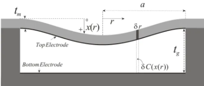
Fig. 1. CMUT Geometry
A Novel Equivalent Circuit Model for CMUTs
H. Kagan Oguz, Selim Olcum, Muhammed N. Senlik, Abdullah Atalar and Hayrettin KöymenDept. of Electrical and Electronics Engineering Bilkent University
Ankara, Turkey 06800 Email: [email protected]
Abstract—A nonlinear equivalent circuit for immersed transmitting capacitive micromachined ultrasonic transducers (CMUTs) is presented. The velocity profile across the CMUT surface maintains the same form over a wide frequency range. This property and the profile are used to model both the electromechanical conversion and the mechanical section. The model parameters are calculated considering the root mean square of the velocity distribution on the membrane surface as the through variable. The new model is compared with the FEM simulation results. The new model predicts the CMUT performance very accurately.
Keywords-cmut; nonlinear model; velocity profile; root mean square velocity; harmonic distortion
I. INTRODUCTION
Finite element method (FEM) transient analysis is particularly useful to examine the nonlinear behavior of CMUTs. However, it is much more time consuming than other analyses, such as harmonic analysis. On the other hand, equivalent circuit models are also employed to predict the CMUT performance in a much faster and intuitive way [1]-[4]. Inadequacy of these models becomes apparent either when large excitation signal is applied or when the CMUT is immersed into water. In this paper, we focused on improving the equivalent circuit of the CMUT by utilizing its velocity profile and the corresponding radiation impedance.
II. NONLINEAR ANALYTICAL EQUIVALENT CIRCUIT
Mason’s mechanical LC section is widely employed in the equivalent circuit of CMUTs, where L and C represent the equivalent mass and the stiffness of the membrane, respectively [2]. The through variable of this circuit is assumed to be the average particle velocity along the surface of the circular CMUT. Total force on the membrane is generated at the mechanical port of the electromechanical transformer and applied across the mechanical impedance.
In Mason’s equivalent circuit, the turns ratio of the electromechanical transformer, the spring softening capacitance and the shunt input capacitance are carried out by parallel plate and small signal assumptions. When deriving the LC mechanical impedance, clamped membrane boundary conditions are considered, where the reference velocity of the distributed profile is taken as the average velocity.
A. Velocity Profile
The particle velocity profile across a circular clamped radiator is not uniform and can be very well defined by the profiles that Greenspan studied [5]:
2 2 ( ) ( 1) 1 n avg r v r n v a ⎛ ⎞ = + ⎜ − ⎟ ⎝ ⎠ for r a< (1) where a is the radius of the radiator, ris the radial position,
avg
v is the average velocity and n is an integer that determines the structure of the profile. If n=0, then (1) is the velocity profile of a rigid piston and n=2 accurately matches to the profile of a clamped membrane. It is shown using FEM simulations that CMUT can be modeled quite accurately as a clamped radiator over a wide frequency range exceeding twice the series resonance frequency [6]. The displacement profile in (1) can be utilized with n=2 and the total force generated on the CMUT surface can be estimated as a function of the instantaneous peak membrane displacement of this profile, without any simplifying assumptions. Suppose the CMUT is driven by a voltage V t( )=VDC+V tac( ). Then, the electrostatic force acting on a ring of area 2π δ , as depicted in Fig. 1, is r r the derivative of the stored capacitive energy with respect to the displacement normal to the membrane surface, x r t( , ),
[
]
2 d ( ( , )) 1 ( , ) ( ) 2 d C x r t F r t V t x δ δ = (2)where δC x r t( ( , )) is the capacitance of this ring. Integrating (2) across the surface as δ →r 0, yields the total force produced on the membrane [6]:
2193
978-1-4244-4390-1/09/$25.00 ©2009 IEEE 2009 IEEE International Ultrasonics Symposium Proceedings
(
)
1 2 0 ( ) tanh ( ) ( ) 4 ( ) ( ) p g g tot g g p p g x t t t C V t F t t t x t x t t − ⎡ ⎤ ⎢ ⎥ = ⎢ + ⎥ − ⎣ ⎦ (3)where x t is the peak displacement at the center of the p( ) membrane, tgis the gap height, C0 =ε π0 a2/tgand ε is the 0
free space permittivity.
The current passing through the small ring area, 2 r rπ δ , between the CMUT electrodes is the time derivative of the charge confined in this area:
[
]
d[
( ( , ))]
d ( , ) ( ( , ))d ( ) ( ) d d d C x r t V t Q r t C x r t V t t t t δ δ =δ + (4)Integrating the first term in (4) asδr→0 introduces a capacitive current component, Icap( )t +i tc( ), where
0
( ) ( )
cap
I t =C dV t dt and ( )i tc is a nonlinear term,
1 0 tanh ( ) d ( ) ( ) 1 d ( ) p g c p g x t t V t i t C t x t t − ⎡ ⎤ ⎢ ⎥ = − ⎢ ⎥ ⎣ ⎦ (5)
The second term at the right hand side of (4) occurs due to membrane motion and we denote it as the velocity current [6],
1 0 ( )d ( ) tanh ( ) ( ) 2 ( ) d ( ) ( ) p g p g vel p g p p g x t t x t t C V t i t x t t t x t x t t − ⎡ ⎤ ⎢ ⎥ = − − ⎢ ⎥ ⎣ ⎦ (6)
Equations (3), (5) and (6) provide an alternative way of describing the electromechanical conversion present in CMUTs, rather than using an electromechanical transformer. In this way, a dynamic nonlinear transformation takes place, where the velocity profile of the CMUT ismaintained.
B. Root Mean Square (RMS) Velocity and the Corresponding Equivalent Circuit Parameters
The root mean square (rms) velocity across the membrane surface can be defined as
2 2 0 0 1 a ( ) ( ) d d rms v v r v r r r a π θ π ∗ =
∫ ∫
(7) For the velocity profile ( )v r in (1), the peak velocity at the center of the membrane, vp, the average velocity,vavg, andrms v are related as ( 1) p avg v = +n v and 1 2 1 rms avg n v v n + = + (8) Thus, forn=2, the equality vrms 2 =1.8vavg 2 shows that we can express the kinetic energy of the membrane mass as
2 2 2 2 1 ( ) 2 1( )1.8 2 kinetic m rms m avg E t a v t a v ρ π ρ π = = (9)
where ρ is the density, tmis the thickness and ρ π is the tm a2 total mass of the membrane. The value of the mechanical LC parameters and the radiation impedance depend on the definition of the velocity variable used in the equivalent circuit. In Mason’s circuit v is chosen and consequently, L, avg which represents the mass of the membrane, becomes 1.8 times the actual mass. However, in order to conserve the energy when the lumped inductance is exactly equal to the membrane mass, vrms must be employed as the through variable of the equivalent circuit:
2
1.8
rms m
L =L =ρ πt a (10) Furthermore, since the resonance frequency in vacuum must be the same as in Mason’s circuit, the lumped capacitance of the LC mechanical section turns out to be vrms2 vavg 2 times the one obtained by Mason [2]:
(
2)
2 3 0 1 1.8 1.8 16 rms m a C C Y t σ π − = = (11)where σ is the Poisson’s ratio and Y0is the Young’s modulus
of the membrane material. The choice of either vavg or vrms
does not change the resonance frequency in vacuum. However, when the CMUT is immersed, it is crucial to terminate the circuit with the appropriate radiation impedance. The radiation impedance is the ratio of the total radiated power from the device to the square of the magnitude of a nonzero reference velocity. Hence, it is important that the through variable utilized in the model is consistent with the reference velocity used in the radiation impedance. In [5], the radiation impedance of a clamped membrane, ZRavg , is derived by using v and it is significantly different from the avg radiation impedance of a rigid piston, ZRp. Moreover, using
rms
v to calculate the radiation impedance of the clamped membrane, ZRrms , reveals that it is
2 2 avg rms v v times Ravg Z [6].
Fig. 2. The equivalent circuit of an immersed CMUT cell, which is composed of the nonlinear controlled sources that perform the electromechanical conversion and terminated by the radiation impedance related to the profile in (1) for n=2.
In Fig. 2, a nonlinear equivalent circuit of an immersed transmitting CMUT is depicted. In place of an electromechanical transformer the controlled sources implement the equations (3), (5) and (6). Notice that these equations are functions of both the excitation voltage and the instantaneous peak displacement. The mechanical LC section is linear and the radiation impedance isZRrms, so that vrms is the through variable in the entire circuit. This circuit can be simply examined on a time-domain circuit simulator like SPICE. However, ZRrms is defined in the frequency domain and unless a mixed domain simulator is used, the radiation impedance must be approximated as a lumped element equivalent circuit over the frequency range of interest [7].
III. FREQUENCY RESPONSE
A linear pre-stressed harmonic analysis in FEM is a small signal analysis which calculates the frequency response of a
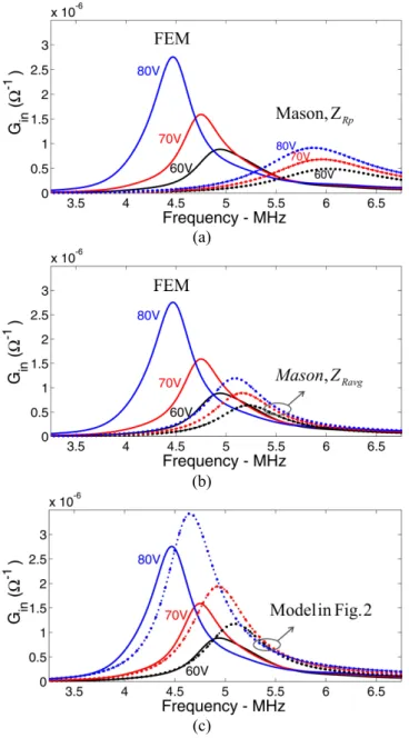
biased membrane. In Fig. 3, we compared the input conductance, Gin,of an immersed CMUT cell as predicted by different equivalent circuits. We used FEM harmonic analysis results as a reference. In Fig. 3(a), the input conductance predicted by Mason’s model, which is terminated by the piston radiation impedance, Z , is given. Results for 1V peak Rp AC signal superimposed on three different bias voltages, 60V, 70V and 80V, are depicted. It can be seen that the resonance frequencies are much lower in the FEM predictions.
In Fig. 3(b), Mason's circuit is terminated with the radiation impedance of a clamped radiator, ZRavg. Since ZRavgis the appropriate radiation impedance for Mason’s model, a certain improvement is obtained.
Both the transformer and the spring softening capacitor in Mason’s model are valid for very small membrane displacement around xp ≈0 , and ignore the fact that membrane is clamped. The proposed model given in Fig. 2 uses controlled sources to provide the electromechanical conversion directly, instead of the transformer and the spring softening capacitor approximation. The prediction of the proposed model is given in Fig. 3(c). The velocity variable is chosen as vrms , where the mechanical and the radiation impedances are employed as explained in Section II-B. The frequency predictions are much closer to FEM.
IV. DISTORTION
The dynamic range of an immersed transmitting CMUT may be defined in several ways. The undesired harmonic energy generated at the driven surface of the membrane and at the output of CMUT can be determined by using the nonlinear equivalent circuit in Fig. 2.
A. Total Harmonic Distortion
Total harmonic distortion (THD) expresses the harmonic content as a percentage of the fundamental component. It can be calculated as, 2 2 2 2 3 1 (%) V V Vm THD V + + + = L (12)
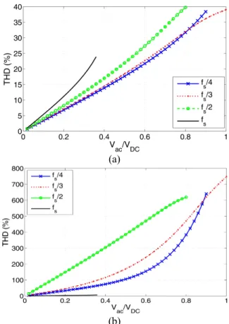
where Vmis the rms voltage of harmonic m and m= stands 1 for the fundamental. Total harmonic distortion in Ftot , generated in the electromechanical conversion and its effect on the acoustic signal observed at the output of the CMUT are shown in Fig. 5(a) and Fig. 5(b), respectively. In the equivalent circuit, the signal radiating to the surrounding medium is found from the force across the radiation impedance. The bias voltage is kept at 50% of the nominal collapse voltage and the driving voltage amplitude,Vac , is increased to its maximum level before collapse.. The model is valid in the frequency range up to about two times the series resonance frequency, fs [6]. Hence, the results which yield harmonics above 2fsand have substantial amount of power
are not reliable. Therefore the analysis is confined to fundamental frequencies up to fs. At fs, the contribution of
the second harmonic to THD is more than 90% of the sum of all other higher harmonics, and they can be ignored.
(a)
(b)
(c)
Fig. 3. Conductance of the CMUT cell in water. 1V peak AC signal is applied at bias voltages 60V, 70V and 80V. FEM (solid) results are acquired from pre-stressed harmonic analysis and compared with the frequency response of (a) Mason’s small signal circuit terminated by
Rp
Z and (b) by ZRavg, and (c) with the proposed equivalent shown in Fig.2.
(a)
(b)
Fig. 5. Total harmonic distortion calculated for (a) the total force driving the mechanical LC section and (b) the acoustic signal radiating to the immersion medium. The model in Fig. 2 is analyzed at 4 different frequencies and theDC bias is 50% of the collapse voltage.
CMUT produces very high distortion at high drive levels, in general. An acceptable linear operation is possible only when the frequency range is confined to a small band aroundfs. It is
observed from the results that THD is especially high when the excitation frequency is half the resonance.
V. CONCLUSIONS
An alternative equivalent circuit for immersed CMUTs is introduced. The electromechanical conversion is directly employed by the controlled sources. The root mean square velocity is chosen as the velocity variable of the model. In this way, both the energy and the mass of the system are conserved in the model. A comparison between other models that use the average velocity definition is presented. Using the model, the nonlinear behavior of the CMUT can be rapidly investigated.
ACKNOWLEDGEMENT
This work is supported in part by Turkish Scientific and Research Council (TUBITAK) under project grants 105E23 and 107T921. SO acknowledges the support of TUBITAK and ASELSAN for their Ph.D. scholarship programs. AA thanks TUBA for the research support.
REFERENCES
[1] I. Ladabaum, X. Jin, H. Soh, A. Atalar, and B. Khuri-Yakub, “Surface micromachined capacitive ultrasonic transducers,” IEEE Trans. on Ultrason., Ferroelec. and Freq. Cont., vol. 45, no. 3, pp. 678–690, May 1998.
[2] W. Mason, Electromechanical Transducers and Wave Filters. 2nd ed. Van Nostrand, New York, 1948.
[3] H. Koymen, M. Senlik, A. Atalar, and S. Olcum, “Parametric linear modeling of circular cMUT membranes in vacuum,” IEEE Trans. on Ultrason., Ferroelec. and Freq. Cont., vol. 54, no. 6, pp. 1229–1239, June 2007.
[4] A. Lohfink and P.-C. Eccardt, “Linear and nonlinear equivalent circuit modeling of CMUTs,” IEEE Trans. on Ultrason., Ferroelec. and Freq. Cont., vol. 52, no. 12, pp. 2163–2172, Dec. 2005.
[5] M. Greenspan, “Piston radiator: Some extensions of the theory,” J. of Acoust. Soc. Am., vol. 65, no. 3, p. 608621, March 1979.
[6] H. K. Oguz, S. Olcum, N. Senlik, V. Tas, A. Atalar and H. Köymen, “Nonlinear Modelling of an Immersed Transmitting Capacitive Micromachined Ultrasonic Transducer for Harmonic Balance Analysis,” submitted for publication in IEEE Trans. on Ultrason., Ferroelec. and Freq. Cont.
[7] A. Bozkurt and M. Karaman, “A lumped circuit model for the radiation impedance of a 2D CMUT array element,” in IEEE Ultrasonics Symp., vol. 4, Sept. 2005, pp. 1929–1932.