MECHANISM OF TRIBOELECTRICITY: A
NOVEL PERSPECTIVE FOR STUDYING
CONTACT ELECTRIFICATION BASED ON
METAL-POLYMER AND
POLYMER-POLYMER INTERACTIONS
a thesis submitted to
the graduate school of engineering and science
of bilkent university
in partial fulfillment of the requirements for
the degree of
master of science
in
materials science and nanotechnology
By
Umar Gishiwa Musa
August 2016
MECHANISM OF TRIBOELECTRICITY: A NOVEL PERSPEC-TIVE FOR STUDYING CONTACT ELECTRIFICATION BASED ON METAL-POLYMER AND POLYMER-POLYMER INTERAC-TIONS
By Umar Gishiwa Musa August 2016
We certify that we have read this thesis and that in our opinion it is fully adequate, in scope and in quality, as a thesis for the degree of Master of Science.
Hasan Tarik Baytekin(Advisor)
Eda Yılmaz
Akin Akda˘g
Approved for the Graduate School of Engineering and Science:
Levent Onural
ABSTRACT
MECHANISM OF TRIBOELECTRICITY: A NOVEL
PERSPECTIVE FOR STUDYING CONTACT
ELECTRIFICATION BASED ON METAL-POLYMER
AND POLYMER-POLYMER INTERACTIONS
Umar Gishiwa Musa
M.S. in Materials Science And Nanotechnology Advisor: Hasan Tarik Baytekin
August 2016
The static electricity that is generated when two identical or different materials come in contact with each other and separated is a well known physical phe-nomenon that has been studied for over 25 centuries. Contact charging occurs in technological and natural aspects of our everyday life. Generation of light-ning and the feeling of unexpected shocks on dry days are excellent examples of naturally occurring phenomenon, while in technology it is used for photocopy-ing and laser printphotocopy-ing. Owphotocopy-ing to the increase in energy consumption around the globe and demand for carbon emissions free energy sources, the triboelectric effect has recently being utilized as an effective means of harvesting mechanical energy and converting it into electricity for novel applications like powering portable electronic devices and self powered active sensing. Despite the fact that it has been known and applied for many years, the fundamental mechanism of contact electrification is still not fully understood.
This study proposes a mechanism for triggering such triboelectric charge based on polymer-polymer and metal-polymer interactions. Conventionally, the mech-anism of electrostatic charge generation is being presumed as a process giving rise to a combination of positive (arising from contact) and negative (arising from separation) charges in every single contact and separation. However, in our mechanism we propose a concept that shows combination of both positive and negative charges as “contact” and either positive or negative charge, depend-ing on the initial contact-charge polarity of the material (due to surface charge mosaic), as “separation” charge. Different kinds of polymers like polydimethyl-siloxane (PDMS), polytetrafluoroethylene (PTFE), Polyethersulfone (PES) and polypropene (PP) were used in this study and similar characteristic was observed
iv
for all of the polymers. Thus, our perception of the working principle of triboelec-trification between two dielectric materials or a metal and a dielectric material is consistent and potentially vital in comprehending some unresolved controversies on triboelectricity.
Keywords: Contact electrification, Mechanism, Triboelectricity, Polymer, Tribo-electric charge, Contact and Separation.
¨
OZET
TR˙IBOELEKTR˙I ˘
G˙IN MEKAN˙IZMASI:
METAL-POL˙IMER VE POL˙IMER-POL˙IMER
ETK˙ILES
¸ ˙IM˙I TABANLI KONTAKT
ELEKTR˙IKLENMEDE YEN˙I B˙IR KONSEPT
Umar Gishiwa Musa
Malzeme Bilimi ve Nanoteknoloji, Y¨uksek Lisans Tez Danı¸smanı: Hasan Tarik Baytekin
A˘gustos 2016
˙Iki aynı veya farklı t¨ur maddeden olu¸san y¨uzeyin birbirine dokundurulup uza-kla¸stırlması sonucu olu¸san statik elektrik, 25 y¨uzyıldan beri ¸calı¸sılmakta olup ¸cok iyi bilinen fiziksel bir olgudur. Kontakt y¨uklenme g¨unl¨uk ya¸samımızda bir ¸cok do˘gal ve teknolojik varlıkta meydana gelmektedir. Kontakt elektriklenme fo-tokopi ve yazıcı teknolojisinde kullanılır, g¨oky¨uz¨unde ¸sim¸sek olu¸sumu ve cisimler arasında meydana gelen beklenmedik elektrik ¸sokları ise kontakt elektriklenmenin do˘gadaki m¨ukemmel ¨ornekleridir. D¨unyada enerji t¨uketiminin ve karbon emisy-onu yok olan kaynaklara ihtiyacın artmasından dolayı son yıllarda triboelektrik, ta¸sınabilir cihazların ¸sarj edilmesi ve kendi kendini ¸sarj eden sens¨orler gibi yeni uygulamalar i¸cin mekanik enerjiyi elektrik enerjisine d¨on¨u¸st¨urmede etkili bir yol olarak kullanılmaktadır. Yıllardır biliniyor ve kullanılıyor olmasına ra˘gmen, kon-takt elektriklenmenin mekanizması halen tam olarak a¸cıklı˘ga kavu¸smamı¸stır.
Bu ¸calı¸smada metal-polimer ve polimer-polimer etkile¸simi tabanlı yeni bir triboelektrik tetiklenme mekanizması sunulmaktadır. Geleneksel olarak elektro-statik y¨uk olu¸sumu, pozitif y¨uk¨un kontakt sırasında olu¸sması ve negatif y¨uk¨un ise ayrılma sırasında olu¸sması proseslerinin bir kombinasyonu olarak kabul edilmek-tedir. Bu tezde sunulan mekanizmada ise, pozitif ve negatif y¨uk olu¸sumları kombinasyonunun y¨uzeylerin kontakt sırasındaki y¨uk polaritesine (mozaik y¨uzey y¨uk modeli) ba˘glı olarak hem kontakt hem de ayrılmada g¨or¨ulebilece˘gini g¨ostermekteyiz. Bu ¸calımada, polidimetilsiloksan (PDMS), politetrafloroetilen (PTFE), polieters¨ulfon (PES) ve polipropilen (PP) gibi farklı t¨ur polimerler kul-lanıldı ve her bir polimer i¸cin benzer ¨ozellikler g¨ozlenmi¸stir. C¸ alı¸smamızda, iki
vi
dielektrik ya da bir dielektrik ve bir metal arasındaki triboelektriklenme mekaniz-ması i¸cin sundu˘gumuz yeni bakı¸sın ge¸cerlili˘gi g¨osterilmi¸stir ve bu bakı¸s, triboelek-triklenme konseptinde var olan tartı¸smanın a¸cıklı˘ga kavu¸smasında b¨uy¨uk ¨oneme sahiptir.
Anahtar s¨ozc¨ukler : Kontakt elektrikleme, Mekanizma, Triboelektrik, Polimer, Triboelektrik Y¨uk, Temas ve Ayrlma..
Acknowledgement
I would like to express my gratitude to my advisor, Asst. Prof. Dr. H. Tarik Baytekin for his enthusiastic support and guidance throughout my thesis. He has given me all the essential advice and inspiration throughout my course of study. I believe his passionate research techniques will have numerous contributions to my scientific prospects. I would also like to thank my co-advisor, Prof. Mehmet Bayindir for his effort and support in this scientific journey.
My special thanks to Dr. Mehmet Kanik for his advice, motivation and con-fidence in me during this expedition. I am grateful to Mrs. NeS¸e ¨Ozg¨ur for her fervent support throughout this journey. I would love to express my sincere appreciation to Muhammad Yunusa and Pınar Beyaz kılı¸c for their assistance throughout this journey. I would like to thank the rest of my office mates, former and present research colleagues; Mustafa ¨Urel, Ahmet Faruk Yavuz, Mehmet Gi-ray Say, Zelal Yavuz, and Doruk Cezan for having good times together and being helpful to one another.
I would like to express my sincere gratitude to some of my friends who are like brothers to me and have tirelessly helped me not only academically, but also intel-lectually. In particular Abba Usman Saleh, Abubakar Isa Adamu, Shettima Sani Dambatta, Abdullahi adamu, Oyewole Benjamin Efunbajo, Adamu Abdullahi, and Musa Abdullahi. I would like to thank the entire National Nanotechnology Research Center (UNAM) family for their support.
Last but not the least, words are powerless to express my gratitude to my beloved family, especially my parents who have had sleepless nights to see my success every now and then. I am so grateful to them, including my brothers and sisters for their prayers and support in my everyday activities.
Thanks to Scientific and Technological Research Council of Turkey (T ¨UB˙ITAK), who supported this work under project no: 214M358.
Contents
1 Motivation 1 2 Introduction 3 2.1 Triboelectricity . . . 3 2.1.1 History of triboelectricity . . . 5 2.1.2 Triboelectric effect . . . 6 2.1.3 Consequences of tribo-effect . . . 72.2 Theory of the Charge transfer mechanisms . . . 10
2.2.1 Electron transfer . . . 12
2.2.2 Ion transfer . . . 15
2.2.3 Material transfer . . . 15
2.3 Triboelectric series . . . 16
3 Contact electrification and tribocharge generation for metal-polymer and metal-polymer-metal-polymer interactions 18
CONTENTS ix
3.1 Introduction . . . 18
3.2 Experimental Section . . . 22
3.2.1 Polymer film preparation . . . 22
3.2.2 Voltage and current measurement . . . 22
3.2.3 Surface characterization . . . 25
3.3 Results and discussions . . . 25
3.4 Mechanism of contact electrification . . . 37
3.4.1 Mechanism of metal-polymer tribocharging . . . 38
3.4.2 Mechanism of polymer-polymer tribocharging . . . 48
4 Conclusion 51
Bibliography 52
A Arduino codes 63
B Device control system 65
C Circuit diagram 66
List of Figures
2.1 Naturally occurring and technologically applied triboelectric phe-nomena . . . 4
2.2 Energy harvesting from water-flow and human-mouth wind . . . . 9
2.3 Other examples of energy harvesting devices . . . 10
2.4 Surface charge transfer between metal-metal contact. . . 12
2.5 Surface states of metal-polymer, before and after contact. . . 13
2.6 Surface states of polymer-polymer, before and after contact. . . . 14
2.7 Triboelectric series of some materials . . . 17
3.1 Unexplained literature results showing our proposed mechanism . 20
3.2 More literature results practically showing our proposed mechanism 21
3.3 Mechanical tapping device for electrical characterization of poly-mers using contact electrification. . . 24
3.4 Measurement setup for the experiment: (a) Output voltage mea-surment. (b) Short circuit current measurement. . . 24
LIST OF FIGURES xi
3.5 Contact and separation signals obtained from interaction between 12 mm diameter aluminium metal and two different 18 mm di-ameter polymers (PDMS and PTFE) at low, moderate, and high frequencies . . . 27
3.6 More results of interaction between 12 mm diameter aluminium metal and eight different 18 mm diameter polymers at low fre-quency for verification of our proposed contact electrification mech-anism . . . 29
3.7 Signals showing positive charge from interaction of metal with (a) PC and (b) Nylon at low frequency. . . 29
3.8 Detailed information of the contact and separation between PDMS and aluminium metal, clearly showing CE, SE, convergence and divergence induction (Icand Id) on both materials during and after
contact. (a) Overall signal (b) Signal from base electrode (c) Signal from metal electrode. . . 30
3.9 XPS surface analysis of PDMS and Al after contact and separation, for investigation of material transfer and separation energy . . . . 32
3.10 Short circuit current and open circuit voltage obtained from thick-ness test of PDMS in contact with Cu metal at 1.0 and 10.0 Hz, respectively. Results from contact between Cu metal and PDMS of thickness: (a) 0.15 mm, (b) 0.24 mm, (c) 0.41 mm, and (d) 0.55 mm. . . 35
3.11 Open-circuit voltage, short circuit current and power density de-pendence on thickness, and output power versus relative humidity relations . . . 37
3.12 Proposed mechanism of contact electrification based on metal-polymer interaction at low and moderate frequency . . . 40
LIST OF FIGURES xii
3.13 Behaviour of the signals after first contact and separation based on metal-polymer interaction at low and moderate frequency contacts, where not only separation (SE) and contact (CE) electrification signals are obtained but also charge induction signals appear while the materials are converging and diverging . . . 42
3.14 Overall outcome of metal-polymer contacts with their respective channel signals . . . 43
3.15 Design of contact base electrode with polymer diameter 12 mm and metal electrode of metal electrode of 6 mm diameter. (b) Picture showing BE with polymer thin film and ME . . . 45
3.16 Electron transfer from polymer to metal contact electrification with LED connected . . . 47
3.17 (a) Samples used. From left to right; (i) Pure PDMS, AuNp-PDMS composites (ii) 0.5, (iii) 0.99, (iv) 1.96 and (v) 3.85 % of Au in 1 gram of PDMS each. (b) SEM images of pure PDMS at magnification of 564 x, and (c) Au doped PDMS (5 mg Au in 1 gram of PDMS = 1.96 %) with 539 x magnification and the percentages of gold in 1 gram of PDMS. . . 49
3.18 Signals obtained by doping pure PDMS samples with Au of 0, 0.5, 1.0, 1.96, and 3.85 Au% in 1 gram of PDMS with their average output voltages. . . 50
B.1 Electronic components used in control system of our device . . . . 65
C.1 Electronic circuit used for constructing the ON-OFF switching sys-tem of our tapping device. . . 66
List of Tables
3.1 Output voltage obtained from each peak during contact and sepa-ration between metal electrode and PDMS . . . 31
Chapter 1
Motivation
The aim of this study was to investigate the fundamental mechanism of tribo-electricity using metal-polymer and polymer-polymer contact electrification/tri-bocharging. The theory of contact electrification; i.e. the history, triboelectric effect, its consequences, and the available charge transfer mechanisms were vig-orously studied before carrying out experimental works. This study has led to a discovery of a new mechanism, which is contrary to the all available contact electrification mechanisms in the literature. It is generally believed that the fun-damental mechanism of electrostatic generation is a process that produces positive charge during contact between two materials and negative charge during separa-tion in one complete oscillasepara-tion, but after thorough investigasepara-tion we realised that the phenomenon is really misunderstood.
Literature results have shown that researchers usually care about generating high output power only, but do not care about what really ignites the electricity, how is it generated and so on. In an attempt to deeply study the fundamental mechanism of the contact electrification and find answers to some controversial issues, we developed a mechanical tapping device suitable for testing triboelec-tric charge of all kinds of polymers or insulators at any given frequency. While carefully studying the effect we discovered and propose, contrary to the aforemen-tioned theory on contact electrification mechanism, a new mechanism of charge
generation by contact electrification and electrostatic induction. The mechanism indicates a combination of both positive and negative charges during contact and a single positive or negative charge signal (depending on the initial charge polar-ity of the materials in contact) during separation, both of which generate charge induction in subsequent contact/separation just after the initial contact and sep-aration. Certainly, people misconceive or intentionally neglect these observations because numerous data from literature have shown our observed signals, but to the best of our knowledge, no one could explain it.
Chapter 2
Introduction
2.1
Triboelectricity
Every person who has had the encounter of walking across a carpet, mat or floor cloth and felt an unexpected and annoying shock just after touching a metal doorknob, or noticed when a balloon is rubbed against hair it sticks to the hair, has experienced a phenomenon known as contact electrification or triboelectricity.
Triboelectricity is generated whenever two materials rub, slide or roll on each other; thus it is an electrostatic charge generated as a result of contact and separation between two identical or different materials, either metal-dielectric or dielectric-dielectric. Contact electrification (triboelectric charging) occurs as a result of charge transfer between surfaces of two materials after contact and separation [1–4]. It is a widely known physical process which happens in many natural and technological phenomena [5, 6]. Generation of lightning, electrostatic charge in dust explosions caused by interactions between particles [5], the be-haviour of sand storms [6, 7], and volcanic plumes [8, 9] are examples of naturally occurring phenomena [5–9].
In technology, it is applied in electrophotography (laser printing and pho-tocopying), electrostatic coating with powders, electrets (found in many types of equipment e.g. acoustic transducers) and electrostatic filtration and separa-tions [5–7, 10–12]. Figure 1.1 shows some examples of naturally occurring and technologically applied triboelectric effects. In Figure 1.1a,b wind strikes metal blades of a military helicopter while landing on the ground, and volcanic eruption generates lighting by causing ashes to propel into the sky [13]. Charge transfer is initiated after charge is generated when the wind blows and causes sand particles to collide with one another [14].
Figure 2.1: Naturally occurring triboelectric phenomena with dusty environ-ments; (a) Countless small sparks due to grains of sand striking metal rotor blades of military helicopters while landing on the ground in deserts, popularly known as “corona effect” producing mega volts. (b) Incredible lightning flashes generated by volcanic eruption [13]. (c) Energy from hygroelectricity and light-ning. (d) Technological application; xerography.
2.1.1
History of triboelectricity
This phenomenon of generating electric charge by contact and separation between materials is frequently called ‘contact electrification’ or ‘contact charging’, and when the materials are rubbed against each other it can be named ‘frictional elec-trification’, ‘triboelecelec-trification’, ‘triboelectric charging’ or ‘tribo-charging’ [15]. The earliest experiments on triboelectricity were said to have been reported by one of the seven philosophers of early Greece [16], Thales of Miletus, over 25 centuries ago when he demonstrated electrostatic charge generation by rubbing two dielectric materials (amber and wool) [5, 10–12, 16]. Even though there are no written documents supporting the role of Thales in the discovery of this phe-nomenon, he is generally credited with it [10, 16, 17].
Triboelectricity is one of the most aged scientific research fields in the world. In the ancient past, due to its association with rubbing of material on amber, electrostatic effect was popularly known as the “amber effect” [17]. The term “electricity” is derived from the Greek word for amber “elektra” [18], and the word ‘triboelectric’ means ‘rubbing amber’ in Greek (which is a combination of two Greek words tribo, meaning to rub, and “amber”) [19]. Until the seventeenth and eighteenth centuries when various scientists made paramount systematic ob-servations of electrostatic phenomenon, electrostatics was really a static topic.
William Gilbert, who was quite blistering about the “theoretical work” of early Greek scientists for conducting very few experimental work on static electricity [16], demonstrated that many other materials (which he called “electrics”) can generate electricity by rubbing; it is not only amber that has the ability to attract objects when rubbed [19]. Nowadays, Gilbert’s electrics and non-electrics (which are difficult to be electrified by contact) are called insulators and conductors [20].
In the early 18th century, another English scientist “Stephen Gray” discovered that when objects were united together by a metal “electricity virtue” could be transferred from one object to another [19]. He was an active experimentalist of electricity who conducted an experiment that led to the understanding of dis-tinction between insulators and conductors [19, 20]. He realized that conductors
like copper or silver convey electricity, whereas insulators like silk or rubber do not [20].
In 1734, Charles Dufay classified electricity generated by friction into two types, namely; vitreous, which is created on crystals, glass, rock, wool, etc., and resinous produced on materials that are resinous like gum, rubber, paper or silk [10, 19]. Dufay was also the founder of the general principle that says “like charges repel while unlike charges attract each other, and that any force between charged bodies rely on the kind and amount of charge” [19].
Later, Benjamin Franklin introduced the terms “positive” and “negative” charges which substituted Dufay’s designations for vitreous and resinous elec-tricity. He also made a proposal that caused the discovery of a theory “In an isolated or closed system, the algebraic sum of the positive and negative charges is constant”, popularly known as the principle of conservation of charge [19–21].
2.1.2
Triboelectric effect
Triboelectric effect involves the appearance of triboelectric charges with opposite signs at surfaces of the two different materials during and after contact. It can occur at solid-liquid, solid-solid or liquid-liquid interfaces [22–24]. In the case of dissimilar solids, which are originally zero-charged and usually at ground potential [22], it is generally thought that electrical charge is exchanged or transferred from one material to the other whenever they interact [23, 25]. However, Grzybowski and coworkers showed that two identical pieces of polymers (PDMS) can get (+) and (−) charges when they are contacted and separated [26]. As the two materials become oppositely charged, the surfaces obtain a net electric charge which forms electric field in between [22].
Being one of the most ubiquitous phenomena which can explain most of the static electricity generated in our daily life, triboelectric effect has recently been utilized as an effective means of harvesting enormous amount of mechanical en-ergy and converting it into electricity for novel enen-ergy applications like chemical
sensing [27], charging portable electronic devices [28], sustainable power sourc-ing [29], light senssourc-ing [30], magnetic senssourc-ing [31] and other self powered sys-tems [32–34], based on coupling between triboelectrification and electrostatic in-duction [33–36]. These types of power generating devices, called triboelectric nanogenerators (TENGs), are cost-effective, simple and robust for energy har-vesting [33–38]. In TENGs, energy conversion process is achieved by periodic contact-separation (vertical or horizontal) mode based on charge polarization, or sliding mode [39] depending on in-plane charge polarization [40, 41].
2.1.3
Consequences of tribo-effect
Here, we briefly discuss some important consequences and hazards of triboelectric-ity. Despite its usage in technology, contact charging can also be a little menace to humanity; for instance, by causing troublesome electric shocks at homes and work places.
2.1.3.1 Important consequences
As mentioned earlier, triboelectrification has many advantages in technology and few disadvantages such as damage to electronic components. It is applied in many areas of technology like biotechnology for study and manipulations of DNA using electrophoretic and dielectrophoretic forces [42], space applications, electrostatic precipitation and coating [42], pharmaceutical dispersal devices e.g. dry-powder inhalers [43,44], electrostatic separation [45], xerography [46] and digital printing by charging of toner particles [47].
2.1.3.2 Hazards triggered by triboelectric effect
Tribo-effect can create static charge accumulation and their successive discharge, known as electrostatic discharge (ESD), on material surface which can be very harmful in explosive and flammable environments [48]. When the accumulated
charge turns out to be adequately high in such environments, in tens of kilo-volts level, it causes gas failure which results in sparks [6, 48]. Lightning and other natural emissions are often regarded as hazardous to every creature. Elec-trostatic charges are sometimes discrete and undetectable, that is why materi-als that are seemingly safe and benign to naked eyes keep large quantities of charge [10]. Some of the numerous incidents that happened in the past are; sev-eral accidents within the period of 1950-1970 in many industries like chemical, defense and petroleum [49]. In order to avoid Electrostatic Discharge (ESD) effect in electronic industry, some danger prevention measures like the use of Per-sonal Protective Equipment (PPE) [50], standard electrostatic test methods, and shielding packaging for sensitive parts protection from ESD damage when in an unrestrained environment, are taken [51].
2.1.3.3 Some examples of energy harvesting devices
Harvesting mechanical energy from our surroundings is a potent perspective for obtaining cost-effective, maintenance-free, clean, sustainable, and green power source for wearable [52], portable and wireless electronics [53, 54]. Owing to the increase in anxieties about the climatic change and energy crisis, renewable energy technologies have received very much attention. Now, devices that are usually powered by batteries are in serious need of smaller or similar size sus-tainable energy sources, because the development of nano/micro size electronics has decreased power consumption which enable them to be powered by small scale energy harvested from ambient environment [55]. Nowadays, researchers are developing self energy driven shoes for harvest energy from human walking and converting it into electricity for charging portable electronic devices like cell phones [56, 57]. Figure 2.2 shows some triboelectric nanogenerators used for har-vesting energy from water-flow, and wind energy from human mouth. Other examples of TENGs are shown in Figure 2.3.
Figure 2.2: TENG used for harvesting water-flow energy in the water: (a) before working and (b) after working (adapted from [58]). (c) TENG was used for harvesting wind energy from human mouth (d) to drive 10 LEDs [59].
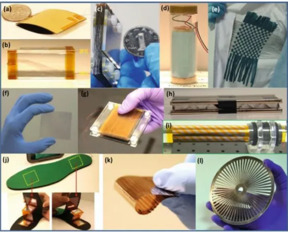
Figure 2.3: Other examples of energy harvesting devices: (a) Finger tapping energy. (b) Air-flow energy. (c) Sliding energy. (d) Enclosed cage for harvesting energy in water. (e) Textile for harvesting body motion energy. (f) Touch pad. (g) Foot or hand pressing energy. (h) Water impact energy. (i) Cylindrical rotation energy. (j) TENG In-sole for harvesting walking energy. (k) Harvesting sliding energy. (l) Rotation energy from disc shape [60].
2.2
Theory of the Charge transfer mechanisms
Despite the fact that triboelectric effect has been known and applied for many years, there is still lack of understanding of the basic mechanisms [61–66]. For instance, the kind of charge carriers or material that is being trans-ferred/exchanged from one surface to another during contact and separation is not clear. Many researchers have classified the tribo-charge transfer mechanisms
into three fundamental processes: electron, ion, and material transfer mecha-nisms [6, 10, 67–72]. Some groups further investigated the happenings on tribo-charged surfaces and concluded that there are other possible processes involved, which include bond-forming, bond-breaking and chemical changes [1, 12, 69–73].
In the following sections, the above mentioned three fundamental mechanisms are discussed based on interactions involving polymeric (or insulating) materials. Contact electrification between two metals is different from the one involving only polymers or metal-polymer, it is well understood [5]. Tribo-charging of metals occurs as a result of transfer or exchange of electrons between them, due to difference in their work functions. Work function is the energy needed to remove an electron from the surface of solid material, usually metal.
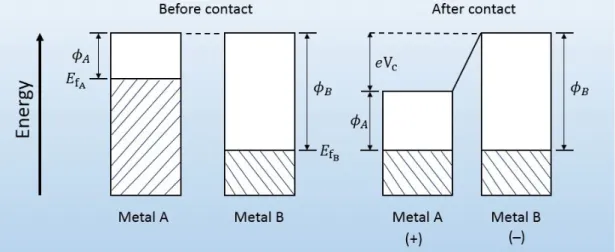
The difference in the Fermi level (or work functions) of metals let electrons flow from the metal with lower work function to the one with higher work function and cross the boundary until their chemical potentials reach thermodynamic equilib-rium [15, 22]. Figure 2.4 depicts a metal-metal surface charge transfer; where “Metal A” with lower work function φA(higher Fermi level “EFA”) becomes
pos-itively charged after making contact with “Metal B” of higher work function φB
(lower Fermi level “EFB”). The transfer of electrons generates potential difference
“Vc” between the surfaces of the metals:
Vc=
φB− φA
e , (2.1)
where e is the electronic charge (e= 1.6 ×10⁻¹⁹ C) [15, 22, 70].
Charge transfer also depends on the effective capacitance of the interface be-tween materials in contact, which is related to their state densities and dielectric constant at the interface. If the charge transfer at the interface is similar to charg-ing of a capacitor with capacitance C, then the process should involve relaxation time “τ ” for it to reach equilibrium condition [22].
τ = RC = ρε, (2.2)
ρ resistivity. In case of highly insulating materials, τ turns out to be extremely large which can avert the attainment of equilibrium state. Charge recombination cannot fully arise if one or both of the materials are insulators, thus the materials hold back their charge after separation [22].
The amount of total charge “Q” transferred after contact and separation can also be determined using the following equation:
Q = C0Vc, (2.3)
where Q is the total charge and C0 capacitance of the system related to contacting
materials.
Figure 2.4: Surface charge transfer between metal-metal contact.
2.2.1
Electron transfer
In the late twentieth century, Lowell and Rose-Innes [72] made a classical review on contact electrification that is full of perceptive insights into the field, more especially about the mechanism of electron transfer. For contact that involves at least a metal or a semiconductor, electron dominates charge transfer in the system. If both materials are polymers (or insulators), then charge carriers alone cannot give an insight about the basic charge transfer mechanism, chemical nature of functional groups need to be examined as well [68, 70]. In theory valence and
conduction bands of insulators may have small amount of charges, but according to Lowell et al. the charges are negligible in experiment if the surfaces of the bands contain some electrons beyond and beneath Fermi level of metal [72].
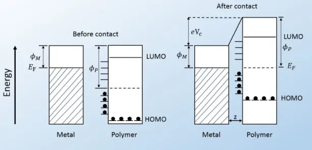
Figure 2.5 shows a model for metal-polymer charge transfer, with z as the intermolecular distance between them after contact where equilibrium is estab-lished, EF the Fermi level of the metal, φM is the work function for metal and φP
for polymer. HOMO is the highest occupied molecular orbitals and LUMO is the lowest unoccupied molecular orbitals. The equilibrium is attained immediately after contact by either replenishing or emptying the electronic orbitals near work function of the polymer, φP [15].
Figure 2.5: Surface states of metal-polymer, before and after contact.
Owing to the absence of free electrons in polymeric or insulating materials, it is still unclear how electron transfer occurs during contact. In insulators, electrons are sparsely arranged due to a large band gap that separates valence and conduction bands which prevents them from flowing [14]. In order to solve the problem of free electrons and pave a way to charge transfer in dielectrics, some researchers [71,72] provided numerous models some of which are similar to metal-polymer contact model with limited flow of electrons in the system [15]. Lowell and Rose-Innes [72] mentioned that, according to thermodynamic equilibrium theory, the charge transfer mechanism between a metal and a dielectric material
in triboelectrification occurs as a result of electron transfer from the metal to the dielectric material (see Figure 2.5 for more detail).
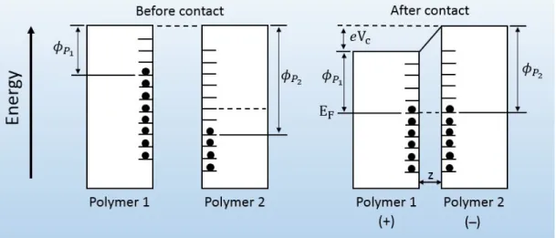
It is generally believed that electron energy levels are not in bulk but present only at the surface of material, as shown in Figure 2.6 where electrons flow from the filled surface of polymer 1 with work function φP1 to the empty space on the
surface of polymer 2 with work function φP2 until equilibrium state is reached
after contact between them. Charge transfer causes equal Fermi energy level “EF” between the two polymers with change in work functions (φP1 and φP2) and
potential difference [15].
Figure 2.6: Surface states of polymer-polymer, before and after contact.
Harper [74] was said to have gathered opinions of some scientists about the conflicting perspectives on charging polymers (or insulators), whether static elec-tricity is generated by ion, electron or both. Loeb claimed that charge carriers are generally electrons, Montmometry said charge carriers are always electrons and Henry thought that the topic was still open for discussion [10]. Recently, new interests have been found on the argument; Baytekin et al. used surface characterization techniques to study the surface composition of the tribo-charged surfaces at nanoscale and concluded that “it is not only transfer of electrons, ions or both that are responsible for contact electrification between the surfaces of materials, it involves spatially inhomogeneous material transfer” [67].
2.2.2
Ion transfer
As earlier stated some researchers believe that contact electrification may involve ion transfer or exchange between surfaces of materials [25, 71, 72, 75, 76]. White-sides’ group [76] proposed ion transfer mechanism and experimentally proved that; for polymers containing mobile ions there is transfer of ions during con-tact. These kinds of insulating materials have bound ions and counter ions with opposite charge polarities that allow the transfer of ions after contact [76]. For metal-polymer contacts only very few ion transfer models are proposed [71].
In the twentieth century, Mizes and co-workers showed that by doping some polymers with ions it is possible to transfer ions from polymer to the metal [25]. Based on their findings some researchers believed that ion transfer is definitely among the general charge transfer mechanisms [74, 76].
2.2.3
Material transfer
In 1967, Harper [74] mentioned that contact electrification may also involve ma-terial transfer in the process. Eleven years later, Salaneck et al. validated how material is being transferred between two contact surfaces (metal-polymer or polymer-polymer) using non-destructive spectroscopic analysis [77]. Salaneck and co-workers also reported that transfer of material decreases as the number of contacts increases subsequently and based on that Lowell assumed that material transfer would not continue if contact is repeated forever [78]. This implies that material transfer is not the main cause of contact electrification.
The transfer involves just pieces of materials on both of the tribo-charged surfaces at nano/micro scales. These pieces of materials have high possibility of taking away charge due to bonds breaking in the contact process [5]. Baytekin et al. validated that contact charging involves both material and charge transfer. They further demonstrated, using polymer films of different compositions, that the charges produced on each surface are both positive and negative (surface
charge mosaic) [12]. Also, our recent XPS (x-ray photoelectron spectroscopy) surface analyses of metal and PDMS after contact have shown that material transfer occurs due to bonds breaking (see results and discussion in chapter 3).
2.3
Triboelectric series
Triboelectric series, named by Shaw in 1917 [5], is a semi-quantitative or quali-tative arrangement of materials based on their tendency to gain either positive or negative charge on contact with other materials [70, 76, 79]. After contact, the material nearer to the top (positive end) of the series will gain positive charge while the one nearer to the bottom (negative end) will gain negative (see Figure 2.7) [76, 80]. The published list in Figure 2.7 is an example of triboelectric series of some materials, adapted from [10] and [76]. For example glass which is very close to the top gain positive charge when contacted with Teflon (PTFE) which is at the extreme end also develops negative charge.
Chapter 3
Contact electrification and
tribocharge generation for
metal-polymer and
polymer-polymer interactions
3.1
Introduction
Concerns over the controversy regarding the mechanisms of contact electrification between metal-polymer and polymer-polymer have led us to a thorough investi-gation of the fundamentals of triboelectricity. In order to answer the questions; how electricity is generated from contact effect, what ignites it, the chemistry and physics behind it, etc., we developed a tapping device for detailed analysis of the basics of contact electrification at low, moderate, and high frequencies.
In this study we discover and propose a new mechanism of charge generation by contact electrification and electrostatic induction. We realised that people gen-erally operate their tapping devices at high frequencies while neglecting the low
and moderate frequencies, thus not being able to observe the fundamental mech-anism of triboelectricity or failing to report the real happenings during contact and separation of materials. In order to clarify the issue, we first discussed the available contact electrification mechanisms in the previous chapter, and here our proposed mechanism is discussed based on experimental evidence in the following sections.
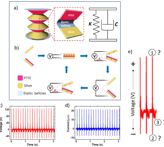
Before proceeding to our proposed mechanism we discuss some literature re-sults that technically verify our findings, but nobody could explain the contact and separation signals in their literature data. They generally focus on the elec-trical performance of their tribocharge generating devices only. Figure 3.1 shows some results with two different categories of peaks, as in our mechanism, indi-cating combination of induction and contact peaks from contact charging and a single peak from separation (see section 3.4 for more information). In Figure 3.1a, they explained only the contact peaks (according to our own mechanism) as their contact and separation peaks while neglecting the real separation peak [81]. Figure 3.1c depicts PDMS-PDMS contact results by Yu et al. showing contact signals highlighted as pressing and releasing, which means contact and separa-tion, while neglecting the actual separation signal with lower output current density [82]. Similar thing is shown in Figure 3.1d from kapton-kapton contact and separation. More literature results are shown in Figure 3.2 with enlarged view of contact and separation signals indicating a combination of positive (1) and negative (2) peaks from contact and a single peak (3) from separation (Fig-ure 3.2e), which we already explained in our mechanism but still pending in the literature. These results have shown that researchers have not figured out what really happen in contact electrification between identical or dissimilar materials. People might not care about the real mechanism because electricity is generated anyhow, but it is very crucial in understanding some contentious issues. Our proposed mechanism is distinctly discussed in section 3.4.
Figure 3.1: Unexplained literature results showing our proposed mechanism: (a) Current density result adapted from [80], showing contact and separation signals separately. (b) output voltage results of triboelectric sensor indicating peaks from contact and a peak from separation [29]. (c) PDMS-PDMS and PDMS with doped AlOx contact and separation, (d) kapton-kapton and kapton-AlOx doped
Figure 3.2: More literature results practically showing our proposed mechanism: (a) The structure of elastic triboelectric nanogenerator. (b) The working mech-anism of the TENG. Output performance of the device; (c) voltage output, and (d) current output. (e) Enlarged view of the first three contact and separation signals of (c), technically verifying our proposed mechanism by showing a combi-nation of positive (1) and negative (2) peaks from contact and a single peak (3) from separation but not explained in the literature [83].
3.2
Experimental Section
3.2.1
Polymer film preparation
Polydimethylsiloxane (PDMS) samples were prepared by mixing and curing meth-ods [84]. The films were produced by thoroughly mixing elastomer and cross-linker or curing agent (purchased from Dow chemical company) at 10:1 weight ratio [84, 85] for about 30 minutes and waited for 2 hours at the ambient lab-oratory environment before heating. The mixture was then heated in an oven under vacuum at 65◦C for 10 hours. After the removal of PDMS films of differ-ent thicknesses from the oven, samples were smoothly laid on the surfaces of Al and Cu SEM stubs of three different diameters (6, 12 and 18 mm, respectively) for contact and experiments. The metals (Al and Cu) were used as supporting and contact electrodes in the experiment. All necessary measures to avoid air interference between metal and polymer were taken. PTFE and the rest of the polymers used were ordered from McMaster. The samples were systematically investigated and demonstrated as instantaneous source in order to measure their output power, open circuit voltage and short circuit current (see next subsection).
At the beginning of this study, the polymers used were only polydimethyl-siloxane (PDMS) and polytetrafluoroethylene (PTFE). We later used polysulfone (PSU), polyvinyl chloride (PVC), polypropylene (PP), kapton, acetate, Polyethy-lene terephthalate (PET), polycarbonate (PC), and Nylon for deeper understand-ing of triboelectric effect and verification of our hypothesis.
3.2.2
Voltage and current measurement
In order to deeply investigate contact electrification at any frequency, we devel-oped a reliable and virtually noise-free mechanical tapping device (Figure 3.3) and designed its control system using microcontroller (Arduino Nano) and some additional electronic components (2N3904 NPN transistor, 1N4007 diode, 1K and
10 K resistors). The codes used for running the tapping device are shown in Ap-pendix A. The control system, the schematic used for building the whole system are shown in Appendix B and C. The device work on horizontal contact mode, with one sample fixed and the other making periodic motion. For instance, in the case of metal-polymer contact all polymers were static on a metal electrode and another metal electrode was making the oscillatory tapping motion.
We measured the open circuit voltage and short circuit current of the polymers using our tapping device at 1, 3, 10, 15 and 20 Hz, respectively. All data were taken using digital oscilloscope (Owon SDS7072 70 MHz, 2+1 Channel, 1 GS/s) with P4100 Series probes (100:1/100 MHz, Input voltage 2KV DC + AC pk, P4100 series High voltage probes), low-noise current preamplifier (SR570 Cur-rent Preamplifier) and transferred to computer for processing. The voltage and measurement setup are designed in Figure 3.4 (see Appendix D for data pro-cessing). 4189 Treacable Humidity/Thermometer-Control company was used to examine the effect of humidity and temperature on the output power throughout this study. The humidity recorded during this analysis fall in the range 13 to 35%, all measured using the above mentioned humidity meter.
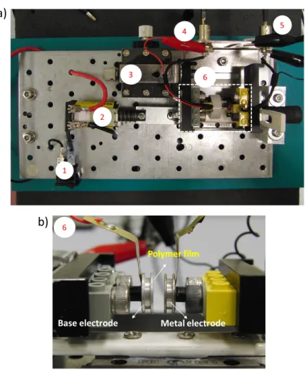
Although there are some results taken from single electrodes, we generally used two channels of oscilloscope to take data from both electrodes simultaneously (base and metal electrodes), not the traditional way of taking data, i.e. connecting one electrode to ground and the other to current/voltage measuring device. In order to have full insight of the fundamental mechanism of contact electrification, the two oscilloscope channels were both connected to ground throughout the experiments to observe good signals from both metal and base electrodes. Figure 3.3a shows how probes 1 and 2 are connected to the base and metal electrodes (contact area). The red crocodile clip is the one connecting base electrode to the oscilloscope channel 1 and the black crocodile clip is the one connecting metal electrode to oscilloscope channel 2.
Figure 3.3: Mechanical tapping device used for electrical characterization of the polymers using contact electrification. (a) Top view of the device; (1) ON-OFF switch, (2) solenoid, (3) XY positioner, (4) probe 1 connected to base electrode, (5) probe 2 connected to metal electrode, and (6) contact area . (b) side view of the contact area.
Figure 3.4: Measurement setup for the experiment: (a) Output voltage measur-ment. (b) Short circuit current measuremeasur-ment.
3.2.3
Surface characterization
To verify whether there is material transfer at the surface of materials after con-tact or not, pieces of PDMS and metal (Al foil) were analysed using XPS after a very soft contact and separation. The XPS used in this study was; Thermo XPS, Model: K-Alpha - Monochromated high performance XPS spectrometer). Also, to verify the existence of Au nanoparticles in PDMS-AuNp doped samples scan-ning electron microscopy (SEM) images of the pure PDMS and all AuNp doped samples were taken using FEI QUANTA 200F scanning electron microscope at high voltage (HV) of 10.0 KV, spot size of 3.0 and 100 microns. The samples were first coated using PRECISION ETCHING COATING SYSTEM with carbon of density 2.25 g/cm3 and acoustic impedance of 2.71 ohms to make the surfaces
conductive and obtain high resolution images.
3.3
Results and discussions
From our results, we have discovered that in every complete cycle of triboelectri-fication; contact gives both positive and negative potential signals in a complete oscillation while separation gives a separate (+) or (−) peak only. However, literature always indicate that contact gives only a positive peak while the sepa-ration gives only a negative in a complete cycle. According to our discovery when two materials (dielectric-dielectric or metal-dielectric) come in contact with each other capacitive charge induction occurs between them which gives rise to elec-tron transfer between the two materials. Obviously, literature studies misinterpret these observations. While in contact back flow of electrons occur from acceptor to the donor (now in need of electrons) which results in positive and negative peaks. This happens as a result of tunnelling of electrons between the surfaces of the materials in contact [71, 72]. The separation part also gives a different peak which is either positive or negative alone depending on the triboelectric charge of the material. We have tested our materials several times and observed similar behaviour. The study was further elongated to different kinds of polymers and
homogeneous contact and separation effects were observed. Here we discuss our experimental results, based on which we designed and proposed a new mechanism in the next section.
Alteration of the tapping frequency led us to perceive that the mechanism of contact electrification (explained in section 3.4) gives something different from what has being in the literature for so long. We noticed that at low frequency the separation signals begin to appear, while gradually increasing the frequency the separation peak moves towards the contact peaks (positive and negative) and finally leave no gap at some certain high frequency. Figure 3.5 demonstrates the results acquired from contact and separation of metal electrode with PTFE and PDMS at low, moderate and high frequency (1, 5 and 15 Hz). As the tapping frequency increases from 1 to 5 Hz, for both PDMS and PTFE contact and separation with metal, contact output voltage signals increase and separation signal moves closer to the contact peaks. At high frequency of 15 Hz, for both polymers, single peak each for contact/separation with induction is observed.
At 1 Hz a delay of about 0.5 seconds was observed between the contact and separation peaks due to low tapping force which keeps the separation a bit far from the contact peaks. By gradually increasing the frequency the separation peak draws closer to the contact peaks, as seen in Figure 3.5 (c), until it completely leaves no distance between the contact and separation (Figure 3.5d) due to high tapping frequency. This implies that from the experimental results it is not only PDMS, which is widely used by experimentalist and has piezoelectric properties as well, that behaves according to our proposed mechanism.
Figure 3.5: Contact and separation peaks obtained from interaction between 12 mm diameter aluminium metal and two different 18 mm diameter polymers (PDMS and PTFE) at low, moderate and high frequencies. a) Chemical struc-tures of; (i) PDMS and (ii) PTFE. (b) At low frequency of 1 Hz separation appears to be far from the contact peaks (i) PDMS and (ii) PTFE. c) As the tapping frequency increases to 5 Hz, for both (i) PDMS and (ii) PTFE, voltage signals increase but separation moves closer to the contact peaks. d) At high frequency of 15 Hz, for both (i) PDMS and (ii) PTFE, single peak with induction combined is observed for each contact/separation.
More results of metal-polymer contacts are shown in Figure 3.6 with PSU, PDMS, PTFE, PVC, PP, kapton, acetate and PET. All the results show negative charge from polymers, and positive from metal electrode. However, Figure 3.7 shows some results that give opposite of the above mentioned results by showing positive from polymers (PC and Nylon) and negative from metal electrode. These results and the numerous data seen in the literature have verified the consistency of our mechanism of contact electrification and tribocharging based on metal-polymer and metal-polymer-metal-polymer contacts. All our metal-polymers show similar behaviour to those in triboelectric series (Figure 2.7).
Figure 3.6: More results of interaction between 12 mm diameter aluminium metal and eight different 18 mm diameter polymers at low frequency for verification of our proposed contact electrification mechanism. a) PSU, (b) PVC, (c) PDMS, (d) PTFE, (e) PP, (f) Kapton, (g) PET, and (h) acetate.
Figure 3.7: Signals showing positive charge from interaction of metal with (a) PC and (b) Nylon at low frequency.
Figure 3.8 illustrates detailed information of contact, separation, convergence induction (Ic) and divergence induction (Id) on both materials during and after
contact between aluminium metal and PDMS. The figure also indicates a clear picture of the overall event in contact and separation with all kinds of polymers. The amount of voltage obtained from each peak is also listed in Table 3.1.
Figure 3.8: Detailed information of the contact and separation between PDMS and aluminium metal, clearly showing CE, SE, convergence and divergence in-duction (Icand Id) on both materials during and after contact. (a) Overall signal
Table 3.1: Output voltage obtained from each peak during contact and sepa-ration between metal electrode and PDMS. (Ic)base: Induction signal for base
electrode at the contact. (Id)base: Induction signal for base electrode at the
sep-aration. (CE)base: Contact electrification signal for base electrode during con-tact. (CE)metal: Contact electrification signal for metal electrode during concon-tact. (SE)base: Separation signal for base electrode during separation. (SE)metal: Separation signal for metal electrode during separation.
The emergence of separation signals could be from the charge carried away by material transfer as a result of bond breaking or bond formation. XPS analysis from few research groups [7, 12, 67] have shown that material transfer occurs be-tween contact materials, and while separating from each other there is possibility of carrying away charges. XPS spectrum of pure PDMS shows C1s (42.9%), Si2p (28.9%) and O1s (28.2%) elemental peaks are shown in Figure 3.9a. We checked possibility of material transfer from PDMS to Al surface by XPS measurement. To do this, PDMS was contacted once with Al surface and separated. Material transfer from polymer to metal is evident from the presence of Si (and O) on the metal surface as shown in Figure 3.9b. This result reveals that breaking of Si-O and Si-C bonds in a 3D networking polymer PDMS takes place and transfer of polymeric material onto Al surface occur.
Figure 3.9: XPS surface analysis of pure PDMS and Al after single contact and separation. a) PDMS has C, Si and O atoms, b) Al surface indicates Silicon peaks due to the material transfer from the polymer
In order to have more perception of contact electrification in relation with change of material thickness we conducted a study by changing the thickness of PDMS. We realised that inductive charge increases with increase in thickness of material and frequency, until a certain point is reached where the open circuit voltage begin to decrease. Figure 3.10 shows some experimental results taken from contact between Cu metal and PDMS of thickness 0.15, 0.24, 0.41 and 0.55 mm.
The graphs in Figure 3.10 indicate how, with increase in frequency from 1 Hz to 9.5 Hz, separation peak nearly disappears or moves very close to the contact peaks. The figure also shows how inductive charge increases with increase in thickness and frequency. With 0.15 mm PDMS at 1.0 Hz a peak-peak voltage of 45.6 V was recorded from contact peaks and 14.4 V from separation, current of 1.8 µA was recorded each from both contact and separation signals. After increasing the frequency to 9.5 Hz at same thickness of 0.15 mm a voltage of 52.0 V was obtained from contact and 8.0 V from the separation, current of 2.0 µA was recorded from contact signals and 1.0 µA from the separation (Figure 3.10a).
After increasing the thickness of PDMS to 0.24 mm, at 1.0 Hz a voltage of 81.6 V was recorded from contact and 21.6 V from separation, current of 2.4 µA was measured from both contact and separation. After the frequency is increased to 9.5 Hz, 125.6 V was obtained from contact and 26.0 V from separation, current of 5.6 µA was recorded from contact and 2.8 µA separation (Figure 3.10b). These results show how output increases with increase in thickness and frequency.
As the thickness is further increased to 0.41 mm (Figure 3.10c), at 1 Hz both the current and voltage from contact and separation increase. When frequency is changed to 9.5 Hz at same thickness the output remains almost the same with an increase in separation peaks. Figure 3.10d shows decrease in inductive charge, contact and separation output after further increasing the thickness to 0.55 mm. This implies that the polymeric material has reached its limit, as stated by Lowell et al. “states that are deep inside bulk of an insulator may not have any impact on contact electrification, because they cannot reach electrons from the contacting metal”. However states which lie near the surface, just as the case of thin polymers, can reach out to the metal because electrons have the ability to tunnel into the polymers around short distances [72].
Figure 3.10: Short circuit current and open circuit voltage obtained from thick-ness test of PDMS in contact with Cu metal at 1.0 and 10.0 Hz, respectively. Results from contact between Cu metal and PDMS of thickness: (a) 0.15 mm, (b) 0.24 mm, (c) 0.41 mm, and (d) 0.55 mm.
To investigate environmental effects on contact electrification some output power test related to humidity and power density dependence on thickness study was conducted. Figure 3.11 illustrates that output performance increases as the thickness increases until 0.41 mm is reached where it begins to decrease. This shows that material thickness has its on limit for obtaining maximum output voltage, current and power density. Humidity test also reveals that the higher the humidity the lower the output power. This probably occurs as a result of moisture in the air which lowers the resistance of material surface by allowing wet conductive water layer over the surface to cause redistribution of charge on the surface.
The output power “P” was calculated from the output voltage “V” and short circuit current “I” measured during contact electrification between 6 mm Cu metal and PDMS of four different thicknesses using the following formular;
P = IV (W att), (3.1)
P ower density = P
contact area (W att/m
2
Figure 3.11: Open-circuit voltage, short circuit current and power density depen-dence on thickness, and output power versus relative humidity relations. a-b) Open-circuit voltage and short circuit current acquired from contact-separation at two different frequencies, 1 and 10 Hz respectively. c) Different power den-sities obtained from metal-PDMS interaction at 0.28 cm2 contact surface area
with respect to change in frequency. d) humidity dependence of output power generation procured from 6 different measurements at 5 Hz.
3.4
Mechanism of contact electrification
Contact charging results in electric potential difference whenever two materials come in contact and separated [79]. Even though triboelectric effect has been known and applied in technology for so long, the fundamental mechanism is still not well understood [67–80]. Based on experimental evidence we designed and explained our mechanism in detail.
We earlier discussed (in chapter 2) the three basic mechanisms in which charge is transferred from one body to another during contact. Charge transfer is usu-ally due to electron transfer in metal-polymer or polymer-polymer contact [72].
Although, other transfer mechanisms may play vital role in exceptional cases like the contact involving insulators with mobile ions [78]. In this section, we discuss our proposed mechanism in detail by using three kinds of contact tapping fre-quency; low frequency (1 Hz), moderate frequency (5-10 Hz), and high frequency (>10 Hz).
3.4.1
Mechanism of metal-polymer tribocharging
After careful study of contact electrification using experimental analysis, here we explain our proposed mechanism using three different classifications: low, moderate and high frequency contact and separation based on metal-polymer triboelectrification.
3.4.1.1 Low and moderate frequency contact
The kind of mechanism designed here occurs for contact electrification at low and moderate frequencies only. Figure 3.12 illustrates the proposed mechanism based on metal-polymer (or insulator) contact and separation. Before the con-tact, materials are at their uncharged state. Positive and negative triboelectric charges are generated on the surface of the polymer as soon as the materials (polymer and metal electrode) touch each other (Figure 3.12d). This charge ac-cumulation is contrary to what many experimentalists think, as explained in the previous chapter (triboelectric series), that every material carries either positive or negative charge alone. However, Baytekin and co-workers [12] used modern characterization techniques to show how both positive and negative charges ap-pear on the surface of either polymers after contact. Negative charges flow from metal electrode (ME) to ground and from ground to base electrode (BE) simulta-neously by contact charging; that is, the negative charge produced on the surface of the polymer is directly transferred to ME which then flows to ground, thereby leaving positive charge on the surface of the polymer alone, and attracting elec-trons from the ground to BE (Figure 3.12e,f ). As the polymer retains its positive
surface charge, BE also retains the incoming ground electrons and no charge flow occurs for a while, as shown in Figure 3.12b (5) and g. There is also back flow of electrons from ground to ME, probably due to tunneling of electron around the interface between contact materials [72]. The back flow occurs simultane-ously together with negative charge compensation from BE to ground (Figure 3.12h,i). Positive and negative charges are regenerated at the interface of the contact materials while they begin to separate from each other, which gives rise to simultaneous flow of charge; from ME to ground and from ground to BE (Fig-ure 3.12l,m). This charge might be as a result of material transferred by bond breaking and formation, which takes away some charges during contact (see ma-terial transfer in chapter 2). Then, negative charges remain on base electrode and surface of the polymer, while positive charge remains on the metal electrode. Af-ter a complete cycle (contact and separation), charges still remain on the surfaces of both materials and base electrode which gradually decay into air after some time (it could be minutes, hours or days), unless if BE and ME are connected to ground where discharge occurs and the system goes back to Figure 3.12a or c.
Figure 3.12: Proposed mechanism of contact electrification based on metal-polymer interaction. (a) Before contact the metal-polymer is at uncharged state. (b) Shows the kind of signals obtained (from b to m) in the whole process. (c) Force is applied, metal electrode approaching polymer (which is static on base electrode). (d) Contact and charge generation; positive and negative triboelectric charges are generated on the surface of polymer. (e) Negative charge flow from the surface of polymer to metal electrode (ME) and (f) negative charge flow from ground to the base electrode (BE) occur simultaneously by contact electrification. (g) Polymer retains its positive surface charge, BE retains the incoming negative electrons, and no additional charge flow at this stage. (h) Back flow of charge from ground to ME and (i) negative charge from BE to ground occur concurrently. (j) ME retains the incoming negative charge, no any charge flow and (k) separation set to begin. (l) Positive and negative charge regeneration occurs at the interface of the contact materials (polymer and metal electrode) due to separation, which gives rise to charge flow; from ME to ground and (m) ground to BE at the same time. (n) Negative charges remain on BE and polymer surface, while positive remains on the surface of ME. (o) Decay occurs gradually and (p) when the system is connected to ground, no charge remains in the system.
After initial contact and separation: During experiment, we discovered that after first contact, before second and subsequent contact and separation, charge inductance occurs at very short distance before the materials (polymer and metal electrode) touch each other and while they are separating from each other. At this very small gap the system behaves like an air-gap parallel plate capacitor [86,87]. Charge induction normally occurs when charged materials approach each other by generating electric field in between them [72]. In contact between metal and polymer, charge induction occurs because the remaining charges on both materials after first contact are being transferred. Figure 3.13a depicts how the signals appear with induction peaks for both contact and separation immediately after initial contact and separation at low and moderate frequencies. Charge induction signals appear while the materials are converging (approaching) and diverging (leaving) each other. When force is applied materials start converging each other and no signals appear before initial contact. Signals C1 appears during the initial contact, and signals S1 during separation (Figure 3.13a(ii) and (iii)). Convergence induction (Ic) occurs at a very small distance while the materials
are converging each other for second contact. The Ic together with the contact
give rise to a combination of induction and contact signals C2 (Figure 3.13a(iv)). As the materials start diverging from each other the separation and divergence induction (Id) signals S2 appear, as shown in Figure 3.13a(v)). After the first
contact, all subsequent contact and separation give similar results as in C2 and S2 which are also similar to C3 and S3. The signals observed are also separated according to oscilloscope channels 1 and 2 in Figure 3.13b,c for clear description of the mechanism.
Figure 3.14 demonstrates the overall signals of metal electrode and polymer obtained at 1 Hz, where the individual channels are plotted separately for clear explanation of the signals obtain at low and moderate frequencies. Figure 3.15 also gives the overall results of the happenings at low, moderate and high fre-quencies (1, 5, and 10 Hz). The results show how convergence and divergence induction appear after first contact.
Figure 3.13: Behaviour of the signals after first contact based on metal-polymer interaction at low and moderate frequency contacts, where not only separation (SE) and contact (CE) electrification signals are obtained but also charge induc-tion signals appear while the materials are converging and diverging. (a) First, second, and third contact and separation of metal and polymer with their sig-nals: (i) When force is applied materials start approaching each other and no signals obtained. (ii) First contact occurs with contact signals C1, and (iii) first separation occurs while the two materials are diverging from each other which produces signals S1. (iv) Charge induction (Ic) occurs at a very small gap while
the materials are about to touch each other, and (v) second contact occurs im-mediately, giving rise to a combination of induction and contact signals C2. (vi) Second separation occurs while the materials are separating, thereby generating separation and divergence charge induction (Id) signals S2. (vii) Third contact
and separation gives similar signals C3 and S3 with second contact, which is same for every contact/separation after the initial contact and separation. Sig-nals observed from oscilloscope channels 1 and 2: (b) Oscilloscope channel 1, connected to BE and polymer, shows all the signals obtained in (a) via channel 1. (c) Oscilloscope channel 2, connected to ME, indicates all the signals obtained
Figure 3.14: Overall outcome of metal-polymer contacts with their respective channel signals. (a) Overall signal for for subsequent contacts at 1 Hz. (b) signals recorded from base electrode (channel 1). (C) signals obtained from metal electrode (channel 2).
3.4.1.2 High frequency contact
We discovered that at high frequencies (>10 Hz) the observed signals appear as a combination of two peaks; a single peak from contact and a single peak with opposite polarity from separation. The results in Figure 3.15g,h have clearly shown the occurrences at high frequencies, where convergence induction, diver-gence induction, contact and separation signals merge together due to high tap-ping frequency (Ic+CE+SE+Id). Prior to contact, materials are at uncharged
state. Thus, at high frequency Ic and CE combine to form a single peak
(ap-peared as positive signal in Figure 3.15g), while SE and Id combine to form a
single peak of opposite polarity (appeared as negative signal in Figure 3.15f ). This is the reason why contact electrification cannot be regarded as a process that gives rise to only positive peak during contact and a negative peak during separation. Thus, we have clearly shown how people unknowingly concluded that contact and separation between two materials gives only two peaks (positive and negative).
Figure 3.15: (a) Design of contact base electrode with a polymer of diameter 12 mm and Cu metal electrode of 6 mm diameter. (b) Picture showing BE with polymer thin film and ME. (c,d) Results showing three peaks from combined CE and Ic signals and separation signals (SE and Id) at 1 Hz. (e,f) Shows Ic and CE
combined, while separation signals move closer to contact as a combination of Id
and SE at 5 Hz. (g,h) Now all the signals appear as a single signal of two peaks (Ic
+CE+ SE+Id). This is the common signal in the published results which cause
a big confusion in assigning the contact-separation electric signals. (PP was the polymer used to show the general behaviour of contact and separation peaks at low, moderate and high frequencies for all kind of polymers).
3.4.1.3 Evidence of electron transfer from polymer to metal
We used light emitting diode (LED) in forward and reverse connections to verify our proposed triboelectrification mechanism. The forward polarity of the LED is a way of connecting the Anode (+) of the LED to metal electrode and the Cathode (−) to ground, while the reverse polarity is a way of connecting Cathode to the metal electrode and Anode to the ground.
We tested the LED using contact and separation between PTFE and Cu metal. Based on our mechanism, we connected the Cathode (−) of the LED to the metal electrode (reverse polarity) and observed light as the polymer touched the metal surface (Figure 3.16a (i)). When the metal electrode is connected to the Anode (+) of the LED (forward polarity) no light was observed, as shown in Figure 3.16a (ii). However, according to a large number of published results in the literature and [60], [72] electron transfer from metal to polymer is regarded as the only possibility of charge transfer between the metal-polymer, transfer from polymer to metal is accepted as impossible. Also, after separation light was observed from forward polarity which verifies transfer of electrons from polymer to metal during contact (Figure 3.16b (i)), and no light was observed after separation in the reverse polarity which indicates that no transfer of electron from metal to polymer.
Figure 3.16: Electron transfer from polymer to metal contact electrification with LED connected: (a) During contact in (i) reverse polarity and (ii) forward polarity of the LED. (b) After separation in (i) reverse polarity and (ii) forward polarity of the LED

![Figure 2.2: TENG used for harvesting water-flow energy in the water: (a) before working and (b) after working (adapted from [58])](https://thumb-eu.123doks.com/thumbv2/9libnet/5874200.121080/22.918.179.765.393.793/figure-teng-harvesting-water-energy-working-working-adapted.webp)
![Figure 2.7: Triboelectric series of some materials, adapted from [10] and [76].](https://thumb-eu.123doks.com/thumbv2/9libnet/5874200.121080/30.918.215.750.280.949/figure-triboelectric-series-materials-adapted.webp)
![Figure 3.1: Unexplained literature results showing our proposed mechanism: (a) Current density result adapted from [80], showing contact and separation signals separately](https://thumb-eu.123doks.com/thumbv2/9libnet/5874200.121080/33.918.189.772.348.773/figure-unexplained-literature-proposed-mechanism-current-separation-separately.webp)