Localizing the excitation to reduce scan time using nonlinear gradient fields
Emre Kopanoglu1,2, Ugur Yilmaz1,2, Burak Akin2, Volkan Acikel1,2, and Ergin Atalar1,21Electrical and Electronics Engineering, Bilkent University, Ankara, Turkey, 2UMRAM, Bilkent University, Ankara, Turkey
Introduction
In a considerable number of MRI applications such as cardiac MRI and functional MRI, the region of interest (ROI) is merely a small volume inside the imaged volume. When conventional slice/slab imaging methods are employed for such a case, the full-FOV has to be encoded to prevent folding, hence, total imaging time is high. Therefore, alternative approaches such as confining the excitation to the ROI using multi-dimensional excitation pulses and employing specific radiofrequency coil arrays have been developed. However, a significant increase in SAR accompanies the time reduction in the former and the latter is not very effective unless the ROI is close to the surface. Although acceleration techniques such as
GRAPPA and SENSE can be used to decrease scan time, such methods yield non-uniform noise amplification in the images.
We have recently shown that nonlinear gradients may provide significant reductions in SAR (Kopanoglu E et al. Proc. ISMRM 19th,
Montreal, 2011; p1848). Another benefit of nonlinear gradients is
confining the excitation along all three dimensions without multi-dimensional excitation. In this study, we show that with nonlinear gradient fields and proper selection of the readout direction, the FOV can be reduced without any folding artifacts, and hence, the total scan time can be reduced.
Theory
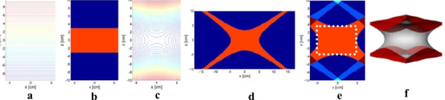
Gradient fields with linear variation in space specify the field distribution along only one direction. Therefore, an RF pulse transmitted in the existence of a linear gradient field (Fig.1a) can specify the excitation region along only one direction (Fig.1b). To confine the excitation pattern along more than one direction, multi-dimensional pulses have to be used, which increase the SAR. On the other hand, gradient fields with higher order variation in space such as z2-x2/2-y2/2 have curved field contours (Fig.1c). Therefore, the excitation pattern due to an RF pulse is confined along more than one direction (Fig.1d). As the RF pulse is still one-dimensional, the SAR is not altered with this method.
For any excitation approach, when the full-FOV is not encoded along one of the perpendicular directions, the data from outside the FOV folds over into the encoded FOV, as is the case for the proposed method (Fig.1e). However, it can be seen that the region indicated with a white dashed rectangle is not affected by the folding, as long as the FOV along the z-direction is large enough. The same concept repeats itself, when the encoding along the second transverse direction is also limited to a smaller region than the full-FOV. In this case, a non-regular region (Fig.1f) that encloses a cylindrical
region with a radius/height ratio of √2/2 remains artifact-free while the FOV along the two transverse directions is reduced.
Methods
To demonstrate the theory, simulations and experiments are performed on Matlab (Mathworks, Natick, MA) and a 3T Siemens TimTrio scanner, respectively. In the experiments, a gradient echo sequence with an apodized sinc pulse as the RF excitation is used. During excitation, all linear gradient fields are turned off. In order to generate the z2-x2/2-y2/2 field variation in space, the A20 shim field of the scanner is used due to the lack of an additional A20 coil and current amplifier. By altering the standard (adjusted during ramp-up) shim current of the A20 coil, the required field is obtained, but because the shim amplifiers are not designed to pump large currents, the highest generated field magnitude is 1.3 mT/m2. Therefore, the
bandwidth of the RF pulse is decreased to achieve a narrow excitation region, which increases the duration of the RF pulse (hence, TE=26ms, TR=40ms). Because this field is on during acquisition too, the voxel sizes are kept small so that the dephasing due to the shim field does not cause intra-voxel signal cancellation (R-L:2.3mm, A-P:1.2mm, H-F:1.2mm). As the excitation region is thick along all directions, 3D encoding (section enc.: R-L, readout: H-F) is used.
The region of interest is selected to include the occipital lobe and the cerebellum in the head. Fig.2a shows the expected fold-over artifact and in Fig.2b, it is superposed on a T1w-MPR image of the same volunteer. The green rectangles in Fig. 2b indicate the extent of the FOV, and the red regions show how the extensions of the excitation region outside the FOV will fold-over. Images from two sections along the slab-selection direction are given in Figs.2c-d.
Results & Discussion
Because the duration of the RF pulse was increased to compensate the low current flowing in the A20 coil, the images in Figs.2c-d are T2*-weighted whereas Fig.2b, which is approximately the same slice as Fig.2d but with 1mm slice thickness, is T1 weighted. However, even though the contrast mechanisms of these images are different, the same anatomical details can be seen upon inspection.
With the proposed method, the FOV along the phase encoding direction (A-P) is reduced to just 10 cm whereas the A-P length of the volunteer’s head was 24 cm. Hence, the total duration of the sequence was reduced by approximately 60% without any fold-over artifacts inside the region of interest. The proposed method does not alter the SAR from that of a one-dimensional excitation, therefore having less SAR than multi-dimensional pulses. However, as number of data points obtained in total is also reduced by 60%, an SNR drop of 37% is expected, which is also the case for multi-dimensional excitation.
Note that, the shim field is always present inside. Hence, some signal is lost beyond the cerebellum. However, with a gradient amplifier that can drive an A20 coil with sufficient current, the proposed method can be combined with any imaging sequence including gradient and spin echo and echo-planar imaging. Furthermore, parallel imaging techniques such as SENSE and GRAPPA can be fused with the proposed method to yield further reductions in total scan time. We are planning to use a custom nonlinear gradient coil through our transmit-array and an additional amplifier, and have started the installation of the necessary hardware.
Conclusion
In this study, a method that reduces the FOV without any folding artifacts and any increase in SAR through the use of nonlinear gradient fields has been introduced.
Figure 1: Field contours for a z-gradient (a) and the A20 field (c) and the excitation profiles obtained with these fields present, using sinc pulses (b and d, respectively). e: Limiting the FOV along the x-direction (e) and both x- and y-x-directions (f) cause folding artifact [blue in (e), red in (f)], whereas the orange and gray regions remain free-of artifact, respectively.
a b c d e f
a b c d
Figure 2: Folding pattern when there are no spins inside the right half of the excitation region (a). The pattern in (a) superposed on the T1w image of the volunteer (b). Images of two sections along the slab encoding direction that show the cerebellum and the occipital cortex (c-d) with (c) being the same slice as the image in (b).