1 (1), 2007, 72-87
©BEYKENT UNIVERSITY
DESIGN OF A COMPUTER CONTROLLED PCB
PROTOTYPE PRODUCTION SYSTEM
Bestami Recep ERGÜN Hüseyin CANBOLAT
besterg@mersin. edu. tr huseyinc@mersin. edu. tr
Mersin University, Electrical and Electronics Eng. Dept., 33343
Çiftlikköy, Mersin,Turkey
ABSTRACT
Mostly, electronic circuit designers need to check the operation of their design on an actual circuit. Conventionally, serigraphy or photo-etching techniques are used for this purpose. Both methods require long time and the use of chemicals. In this work, a computer controlled mechanical system is designed to chip the unwanted copper just around the conduction paths. Simply, the system separates the conduction paths from the extra copper surface on the board. The system requires only a raw PCB. The software developed for the system sends the circuit diagram to the mechanical part to create the conduction paths on the raw PCB. The system is designed as a prototype and tested for some sample circuits. The results are satisfactory for the beginning. However, the accuracy of the system should be improved for better results.
Keywords: Printed circuit board (PCB), edge detection, electromechanical
system, cutter, step motor.
ÖZET
Elektronik devre tasarımında, devrenin sık sık test edilmesi gerekir. Bunun için kullanılan geleneksel metotlar serigrafi ve ışıkla aşındırmadır. Her iki yöntem de uzun zaman alır, ve çevreye ve insan sağlığına zararlı olabilecek kimyasalların kullanılmasını gerektirir. Bu çalışmada, ham baskı devre plakası üzerinde iletim yollarının etrafındaki bakırı kazıyan bilgisayar kontrollü bir mekanik sistem tasarlanmıştır. Sistem için geliştirilen yazılım bir baskı devre paketiyle oluşturulan devre diyagramını mekanik kısma göndererek, ham PCB üzerinde iletim yollarının açılmasını ve gerekli noktaların delinemsini kontrol etmektedir. Bu sistem prototip olarak oluşturulmuş ve bazı örnek devreler için
test edilmiştir. Sonuçlar başlangıç için tatmin edici olsa da, sistemin hassasiyetinin artırılmasına ihtiyaç vardır.
Anahtar kelimeler: Baskı devre plakası (PCB), kenar algılama, grafik dili,
elektromekanik sistem, kesici, adım motoru.
1. INTRODUCTION
Printed circuit board (PCB) technology first introduced by the Austrian engineer Paul Eisler in 1936. It was extensively used by the US military in order to produce more reliable radio receivers. Now, one can produce multilayer PCB circuits [1,2].
The prototypes of electronic circuits should be produced in order to test them for proper operation before mass production. The most common method is to place the components on a breadboard and check the circuit operation applying proper input signals. However, this method is only useful for simple circuits that operate at low frequencies and consume low power. Also any problem due to the breadboard is hard to detect.
Reliable test of circuits can be achieved by producing its prototype on a PCB and fixing the components by soldering. However, conventional methods of photo-etching and serigraphy techniques to transfer the conduction paths onto a raw PCB cost much and are hard [3]. Furthermore, if an error is detected on a prototype, another prototype PCB should be produced for the redesigned circuit in a short time by reproducing the same troublesome steps again. Both serigraphy and photo-etching techniques require the use of some chemicals, which may be dangerous for health and environment due to mistreatment of waste chemicals after the production.
In this work, a computer controlled system is designed for prototype PCB production, which transfers the conduction paths directly on a raw PCb and does not require the use of any chemicals. The system includes both software and hardware. Software part takes the conduction path diagram and send proper commands to the hardware through the paralel port in order to transfer the paths on a raw PCB placed properly in the mechanical subsystem.
2. SYSTEM STRUCTURE AND REALIZATION
System consists of two main parts; software and hardware. In fact, hardware includes both electronic control circuit and a 3-axis electromechanical system.
2.1. GENERAL STRUCTURE of the SYSTEM
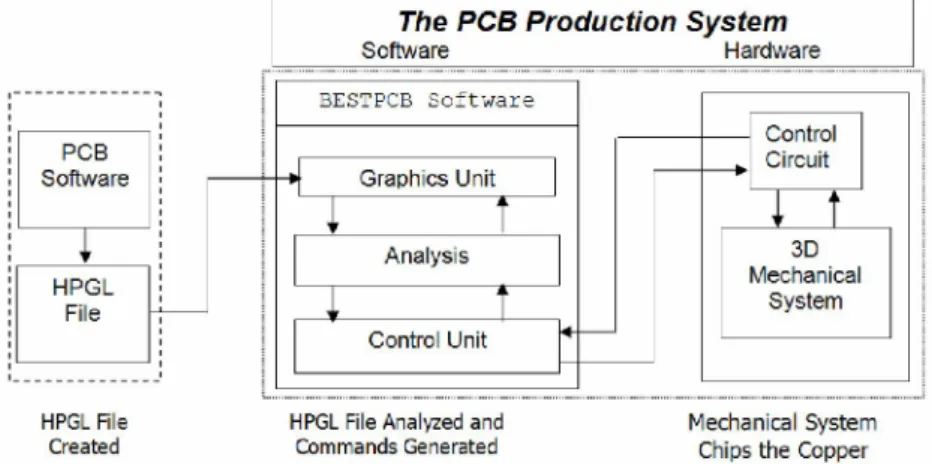
The block diagram of the system is given in Figure 1. The drawing of conduction path diagram should be created using a PCB design software, such as, OrCAD, BoardMaker, ProLite, UltiBoard, and the diagram should be saved in HPGL (Hewlett Packard Graphics Language) [4]. Some softwares may not
support HPGL format. In that case, the circuit path diagram should be sent to a HP plotter, such as, 7470A making the "save as a file" option active. The result will be the circuit diagram file in HPGL. In any case, our BESTPCB software will take the HPGL file as a source. After analysis, the required commands to the mechanical system is sent out through the control cicuit. Then the electromechanical system draws the conduction paths on a raw PCB.
HPGL File HPGL File Analyzed and Mechanical System
Created Commands Generated chips the Capper
Figure 1. The structure of the Designed PCB Production System 2.2. SOFTWARE
The software is developed using Delphi4 environment and it is called BESTPCB. BESTPCB can be run in Windows95, Windows98, Windows98SE, WindowsME, Windows2000, WindowsNT and WindowsXP operating systems.
BESTPCB performs the required operations in several phases. These phases are
• Imaging • Edge detection • Route detection
• Command generation for the control circuit
BESTPCB software takes the circuit path diagram in HPGL format. Every character is read and combined with the previous characters until a valid 2-D HPGL command is obtained. If the combination has no meaning in HPGL, then it is discarded. Valid commands are saved and required variables are assigned for the command. Following command parameters are determined and these data are written to the variables assigned for the command. The corresponding drawing or transfer action dictated by the valid HPGL command is executed on the screen. After this, the remaining code is scanned character by character to obtain other valid HPGL commands in the file and
the functions described above are repeated until the end of file is reached. When the end of file is reached, the imaging process is over.
After the imaging phase is done, the edge detection phase is started. The image on the screen is scanned to detect the edges of the paths. Based on the detected edges, route detection is performed (Figure 2).
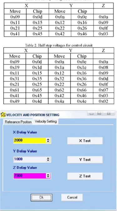
In the last step, the coordinates are transferred to the control circuit via paralel port of the PC in order to control the operation of the electromechanical system, which performs the necessary chipping and making holes on the PCB. The step motor input voltage tables are given for full step and half step in Tables 2.1 and 2.2, respectively. Each code in Tables 2.1 and 2.2 represents an 8-bit data for each step and they are given in hexadecimal format. For example, 00011010=0x1A, where the prefix 0x- denotes that the following number is hexadecimal.
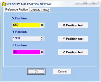
When the system is powered on, the control circuit brings the mechanical subsystem to the initial position via the X-SW and Y-SW switches (Figure 6) according to the values in the "Reference Position" tab (Figure 3). The motor speeds can be adjusted using "Velocity Setting" tab (Figure 4). After the initialization is completed, the motors are driven to chip the extra copper around the conduction paths on the raw PCB placed properly on the mechanical subsystem.
Table 1. Full step voltages for control circuit
X Y Z
Move Chip Move Chip
0x09 0x0d 0x0a 0x0e 0x0a 0x11 0x15 0x12 0x16 0x09 0x21 0x25 0x22 0x26 0x0f 0x41 0x45 0x42 0x46 0x03
Table 2. Half step voltages for control circuit
X Y Z
Move Chip Move Chip
0x09 0x0d 0x0a 0x0e 0x0a 0x19 0x1d 0x1a 0x1e 0x08 0x11 0x15 0x12 0x16 0x09 0x31 0x35 0x32 0x36 0x0d 0x21 0x25 0x22 0x26 0x0f 0x61 0x65 0x62 0x66 0x07 0x41 0x45 0x42 0x46 0x03 0x49 0x4d 0x4a 0x4e 0x02
Vw VELOCITY AHO POSITION SETTING i=i J h L | u
Vw VELOCITY AHO POSITION SETTING
Refeianee Position Velocity Setting
X Delay Value 2000 X Test Y Delay Value 10D0 a • Y Test Z Delay Value 7900
1*1
2 Test \ Ok CancelV i l VELOCITY AHD POSITION SETTING Relerance Position Velocity Setting
C=J Ü=JJ U X Position 650 Y Position 19DD Z Position X Position test Y Position test 33 Z Position test Ok Cancel
Figure 4. Velocity settings tab in B E S T P C B 2.3. CONTROL CIRCUIT
2.3.1. Parallel Port
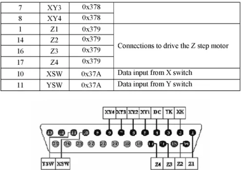
Paralel port has 25 connection points having different functions. These are classified as data, control, and status ports. Seven connections from data port are used to drive the X, Y step motors and the DC motor. Four connections of control port are used to control the Z step motor independently from X and Y step motors. Two connections of status port are used to detect the reference point of the XY-plane [5]. Figure 5. shows the specially structured the paralel port connections for the system. Detailed functions of the connection points are given in Table 3.
Table 3. Selected connections and their functions in the system
NUMBER NAME ADDRESS FUNCTION 2 XK 0x378 Activates the X step motor 3 YK 0x378 Activates the Y step motor 4 DC 0x378 Activates the DC motor
5 XY1 0x378 Common connections to drive the X and Y step motors
6 XY2 0x378
Common connections to drive the X and Y step motors
7 XY3 0x378 8 XY4 0x378 1 Z1 0x379
Connections to drive the Z step motor 14 Z2 0x379
Connections to drive the Z step motor 16 Z3 0x379 Connections to drive the Z step motor 17 Z4 0x379
Connections to drive the Z step motor
10 XSW 0x37A Data input from X switch 11 YSW 0x37A Data input from Y switch
XTJ 3ÍT3 XY2 XYl DC TK XK
f f f f m
©
© ©
YÏW XSW 1A 22 22 21
Figure 5. Parallel port connections structured specifically for the system
2.3.2. Design and Implementation of Control Circuit
The circuit diagram of the control circuit is presented in Figure 6. The circuit is designed to drive the 2-pole permanent magnet X, Y, Z step motors and the DC motor using the hexadecimal codes given in Table 1 and Table 2 [6,7,8,9,10]. The path diagram for the control circuit was prepared (Figure 7) and manufactured using traditional serigraphy technique (Figure 8).
In the circuit, TIP 120 Darlington transistors are employed as switching components. The rated current of these transistors are 5A and they can manage instantanuous currents of up to 8A.
Figure 7. PCB Path Diagram of the Control Circuit
2.3.3. Structure of the Electromechanical System
In this work, the electromechanical system shown schematically in Figure 9 is designed. The electromechanical system chips the copper on the edge of the conduction path to seperate the unwanted copper surface from the paths. The actual system is seen in Figure 10. The system is manufactured to demonstrate that the method proposed in this work can be applicable practically. The control circuit, a switched mode power supply, three step motors, D C motor, axes are placed on a platform. To manufacture the system, available resources are used due to lack of financial support. Therefore, the desired sensitivity could not be achieved experimentally. However, employing more sophisticated components to control the step motors and chipping or melting the copper should allow more complex P C B diagrams are transferred to raw PCB. A PCB produced using the system is shown in Figure 11.
Z stop motor X step
motor
Power supply
Figure 9. AutoCAD drawing of the electromechanical system
Figure 11. PCB samples produced by the system 2.4. ESTIMATION of SYSTEM PARAMETERS
Thoroughout this section, x-step motor, y-step motor, and z-step motor denote the step motors fort he x-direction, y-direction, and z- direction, respectively. Similarly, the subscripts x, y, and z will be used to denote the corresponding values in x-, y-, and z-directions, respectively, without explanation.
The forces acting horizontally (that is, in x- and y- directions) are shown in Figure 12 and the torques of step motors and the frictional forces are estimated (Figure 13) as follows [11]:
n
^{normal f o r c e ) u«
F ^ { a p p l i e d f o r c e ) (friction) (gravityFigure 12.The forces acting in x- and y-directions
2.4.1.The friction force and the rotor torques in x-direction
From Figure 12, the normal force n can be found as
n= mg, (2.1.)
where g=9.81 m/s2 is the gravitational acceleration, and m is the mass which should be moved by the x-step motor. The friction force, f , acts in the reverse direction to the motion and it can be related to the normal force through the friction coefficient ju as follows
The mass, mx, which is the total mass that should be in motion due to
x-step motor, is found to be 2.11kg. The torque, • , exerted by the x-step motor is 0.25Nm. The friction coefficient is taken as ^=0.2. Therefore, (2.1) and (2.2) gives f = 4 . 1 3 N in x-direction. Since the motor should overcome the friction force to obtain a motion, one can use the relation
T=Fxr (2.3.) between the torque and the force, F, acting on the edge of the rotor, where the
symbol x denotes the vector cross product, and r is the radius of the rotor. Since the rotor radius r=7mm and the angle between F and r is 90°, the step motor should apply the force Fx=35.71N.
2.4.2.The friction force and the rotor torques in y-direction
Similar expressions are valid in y-direction except the numerical values, since different step motors are used in x- and y-directions. The following parameters are used in this case:
m=0.75kg U=0.2 g=9.81m/s2
T=0.25Nm r=0.014m
Using (2.1), (2.2), and (2.3) and the above parameter values, it can be found that f , = 1.47N and Fy=17,85N.
2.4.3.The friction force and the rotor torques in z-direction
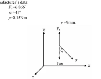
T he force, Fm, that moves the link in z-direction is shown in Figure 14.
The following values can be found through measurements and manufacturer's data: Fz=6.86N a =45° z=0.15Nm r =9mm. Fzm
Figure 14. The force on the link actuated through the z-direction
Using these values, the force, F, which is the force applied by the z-step motor, can be computed using (2.3) as follows;
F=16.66N.
Therefore, the z-direction component, Fzm, of F can be found as follows
Fzm=Fcoso=11.78N.
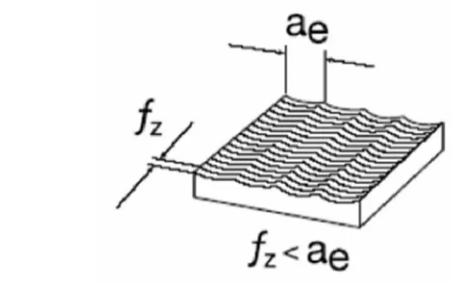
2.4.4.The computations for the boring process
Figure 15, and Figure 16 demonstrates the definitions of boring tool diameter, D, chipping depth, ap, tooth displacement, f , and cutting width of the
boring tool, ae. For more details, the reader is referred to [12,13],
r
tFigure 15. Boring tool diameter, D, and chipping depth, ap The following parameter values is used in the calculations. D=1mm=0.001m
n=8000rpm af=0.5mm ae=1mm Ff=600mm/min
/ z < a e
Figure 16. Tooth displacement, fz, and cutting width, ae
where n denotes the rotating speed of the boring tool, Vf is the boring tool surface or horizontal velcoity, and zn is the number of cutting edges on the
boring tool.
The cutting velocity, Vc, can be computed using the following
equation:
Vc=oDn=25.12 m/min (2.4.)
The volume, Q, of the chipped copper per minute is given by
Q= apae Vf (2.5.)
Using (2.5), Q is found as 300mm3/min.
The boring surface displacement per revolution, fn, is found using the following equation,
Vf
f =
—.J n
n
(2.6.)
(2.6) gives the value fn=0.075mm/rev. The tooth displacement, fz, is computed using
Vf
nZn
(2.7.) as Vc=0.0375mm/rev.
3. RESULTS and DISCUSSION
In the mechanical system, the raw PCB is placed on a platform over which two shafts moves the cutting tool in the xy-plane to chip off the copper around the paths of the generated PCB diagram. Experiments showed that the platform bended about 0.5mm in the z-direction. This deformation results a low quality chipping, since the copper may not be chipped off completely.
To solve this problem, the raw PCB placed on a heavy platform, and the shaft mechanism was redesigned. Also the resolution of the step motors should be improved using a gear mechanism to reduce the distance at each step. The present resolutions of the system are 0.08mm and 0.106mm in the x-and y- directions, respectively.
In the experiments, drill tips of 0.8mm and 1mm thickness were used for chipping off the copper. For better chipping, proper boring tools should be employed in the system.
4. CONCLUSIONS
The designed system aims to transfer the PCB paths on a raw PCB directly without getting into the troublesome chemical processes. It reduces the labour and time required to get a PCb prototype. The system is designed for individuals and small businesses. Therefore, the design is done using simple, easy to find components to reduce the cost. The present product is not satisfctory to get the desired precision in the design, because the implementation of the system was realized using the authors' personal financial resources. Having beter financial resources, a higher resolution and precision can be obtained.
The system requires only the raw PCB. One does not need to use silk clothes, chemicals, and others that are required if the traditional PCB production methods, such as, serigraphy and photo-etching, are to be used. The production of PCB prototype is practical, economical and less time-consuming with the system. It is also more healthy and has no potential chemical wastes to the environment.
The system performance is improved if the following is done properly:
• A special PCB drawing software should be developed fort he system. Present, design uses the designs from the available PCB softwares. This will improve the functionality of the system.
• Instead of chipping of the copper, one can use lasers to corrode the copper from the PCB surface. Lasers improve the system precision and resolution to get more sophisticated PCB diagrams. Laser corrosion will also reduce the mechanical load on the motors, smaller motors can be used and the positioning system becomes more precise by use of microstepping technique for step motors.
• A feedback mechanism can be implemented to detect the end-effector position and produce the correcting control command in case of an error using position sensors. However, in this case the system has to have extra communication channels for sensors. Parallel port will not be sufficient fort his purpose. The system should use the serial port for feedback channel. • Using a microcontroller will reduce the burden on the PC. This also allows the user run another application on the PC while the microcontroller transfers the path diagram on a raw PCB.
• The system can easily be modified to use for educational purposes. • Instead of drill tips, one can place a pen in the mechanical part in order to use it as a plotter.
REFERENCES
[1] Flatt, M.; Printed Circuit Board Basics:An Introduction To The PCB Industry, Backbeat Books, 3rd ed., San Fransisco (1997).
[2] Varteresian, J.; Fabricating Printed Circuit Boards, Newnes Pres (Elsevier Science), Oxford (2002).
[3] Pekmezci, H.; Tüm Yönleri ile Serigrafi, İpekbaskı (Serigraphy, All Aspects), İlke Yayıncılık, Ankara (1992).
[4] Hewlett Packard; The Complete Reference to Hewlett-Packard's Standard Vector Graphics Language, Addison-Wesley Publishing Co., Boston (1990).
[5] Gümüşkaya, H.; Mikroişlemciler ve Bilgisayarlar (Microprocessors and Computers), Alfa Yayıncılık., İstanbul (1999).
[6] Şen, K.; A PC-Based Industrial Position Control System, MSc Thesis at the Middle East Technical University, Ankara (2000)
[7] Görgün, H.; "Step Motor Kullanılarak Plotter Uygulamasının Gerçekleştirilmesi (Realization of a Plotter Application Using Step Motors", MSc Thesis at Yıldız Technical University, İstanbul (1998). [8] Ateş, S. M.; A PC Controlled Three Dimensional Machine Tool Control
System, MSc Thesis at the Middle East Technical University, Ankara (2001).
[9] Kaya, İ.; Mekanik Sistemlerin Step Motorlarla Denetimi (Control of Mechanical Systems via Step Motors), MSc Thesis at Sakarya University, Sakarya (1997).
[10] Taştan, L.; Bilgisayar Yardımı ile Step Motorun Hareket Kontrolü (Computer Control of a Step Motor Motion), MSc Thesis at İstanbul Technical University, İstanbul (1997).
[11] Ural, O.; Fizik I (Physics I), Oran Yayıncılık, İzmir (1992).
[12] Ataşimşek, S.; CNC-Metal İşleme El Kitabı (CNC Metal Processing Handbook), Birsen Yayıncılık, İstanbul (2004).
[13] Gülesin, M., and Güllü, A.; Makina Teknolojileri İçin Birimler, Formüller ve Çizelgeler (Units, Formulae and Tables for Machine Technologies), Seçkin Yayıncılık, Ankara (2003).
[14] Ergun, B. R., and Canbolat, H.; Design of a Computer Controlled Printed Circuit Board Prototype Production System, Proc. of 2nd Int. Symp. on Electrical, Electronics and Computer Eng., Lefkosa 1 (2004), 282-286.
[15] Ergun, B. R., and Canbolat, H.; Design of a Computer Controlled Printed Circuit Board Production System: Electro-Mechanical Subsystem, Proc. of 3rd FAE Int. Symposium, Gemikonagi-Lefke 1 (2004),467-471.