Series: Mechanics, Automatic Control and Robotics Vol. 7, N 1, 2008, pp. 159 - 168
HOMING AIR-DEFENCE MISSILE SYSTEMS USING A NOVEL
FUZZY-LOGIC MODE OF FIRE CONTROL
UDC 623.463:623.465.7+623.55:623.466.5(045)=111
Saso Gelev
1, Zoran Gacovski
2,
Stojce Deskovski
3, Georgi M. Dimirovski
4,51Military Academy “General Mihailo Apostolski”, MK-1000 Skopje, Rep. of Macedonia 2European University - Skopje, MK-1000 Skopje, Rep. of Macedonia
3Technical Faculty, St. Clement University, MK-7000 Bitola, Rep. of Macedonia 4Dogus University, Faculty of Eng., Acibadem, Kadikoy, TR-34722 Istanbul, Rep. of Turkey 5SS Cyril and Methodius University, Faculty of EE & IT, MK-1000 Skopje, Rep. of Macedonia
e-mail: [email protected]; [email protected]; [email protected]; [email protected]
Abstract. The problem of shooting targets in the air isa rather complex task, in which every missile system for air defence is responsible for fire control. In this paper we present a novel approach and mode for fire control in air-defence systems based on homing missiles. A device for calculation of the launching zone (AOZ) is used for intelligent estimation whether the target has entered the launching zone. The proposed novel approach makes essential use of fuzzy reasoning, a fuzzy-rule knowledge base for target’s velocity, to calculate the launching zone immediately upon the first detection of a target. Namely, it uses pre-defined launching zones for different flying regimes and different velocities of potential targets, and the data are stored into a look-up table along with the associated pass angles and flying times to the launching zone border. Computational model for simulation and simulation experiments were carried out using a new model constructed in Matlab-Simulink platform.
Key words: Air defence; early warning; fire control; homing guidance; launching zone estimator; missile system; simulation model
1.INTRODUCTION
The missile system for air defence is used for destroying of air-attacking objects (manned and unmanned flying objects, helicopters, automated balloons etc.) which are attacking our civil and military objects. In some exceptional cases (self-defence or lack of other weapons) the missile system for AD can be applied for destroying of ground (sea) targets. The missile system should have high combat characteristics. The combat actions are guided from a central command post, applying an automated system for fire control and decision-making.
The motivation for this paper arose from the research project 07-1191/4 at the Mili-tary Academy “General Mihailo Apostolski” Skopje and the Faculty for Electrical engineering − Skopje titled “Development and implementation of algorithms for guid-ance, navigation and control of mobile objects”.
In general the fire control system on the command post should solve the tasks listed below:
− Collection and processing of information for the air situation, obtained from differ-ent sources;
− Task understanding; − Estimation of the situation;
− Decision - making for rejecting the air attack; − Defining the tasks for the missile systems; − Control about task execution
The command tasks (for the fire control) are to be solved on a logical manner with the rigid time constraints, since the combat actions of the missile systems are performed very fast, with large tension, dynamics and short time, (as a consequence to the enemy’s different tactics and counter-attacks).
2.THESYSTEM BASICS OF FIRE CONTROL
The main task of the fire control systems (FCS), in general, is to perform a sequence of successive operations in order to calculate the collision point between the missile and the target. In anti-aircraft defence (AAD), the collision between the missile and the target, is rather complex mathematical and physical problem, which can be solved with several subsystems, automatically integrated in the missile weapon (Davis et al. 1958; Peresada, 1973; Neupokoev, 1970; Malygin, 1978; Deskovski et al. 2003, 2005).
If we consider the fire control of a single weapon, then we can observe several phases:
The first thing that we should do is early detection of the target and transfer of its rough coordinates to the devices for correct measurement of the coordinates. The target detection can be performed with special radar systems, by visual observing of the air space (human observers) or some other method, and it is followed by alarming of the units and their pointing out in the correct direction.
The second phase is correct measurement of the target coordinates and their transfer to the computer of the fire control system.
The third phase consists of a transformation of the target parameters. If the obtained coordinates of the target are not in the same coordinate system as the fire control com-puters’ - they have to be transformed.
The next phase is consisting of determining the law of change of the target coordi-nates with time, and calculation of the parameters of its movement. In mathematical terms, this task means derivation, i.e. determining of coordinate change dynamics.
The fifth phase of the control task consists of determining of the collision point (in the air) between the missile and the target. To solve this task – it is not enough to know only the current coordinates of the target and its movement parameters in the current moment. We have to start from some hypothesis about target movement law, during the flight of the missile towards it.
The sixth phase consists of determining of the ballistics variables that are necessary for guiding of the launching device towards the collision point between the missile and the target. These variables are calculated for normal shooting conditions. (Under normal conditions we assume the atmosphere is static, there is no wind, the air density is 750 mm Hg, and the air temperature is 150C, - and the missile has nominal ballistics characteristics).
In the real combat situation, the actual conditions are usually different from the nor-mal ones. Also, we have to take into consideration the meteorological and ballistic corrections in order to compensate the difference between the real and the normal condi-tions.
In the guided missile systems, there are two additional phases. The first phase consists of determining the most rational moment for missile launching. During the shooting with water missiles – the probability of destroying the target with one missile is high, and the price of each launching is very high, so we have to solve the task for determining the most suitable moment for missile launching. The launching moment is computed from the conditions for maximal probability of target destruction with one or two missiles. The last phase is closely related with fire control task for the distant missiles, and it consists of the calculation of guiding commands for the missile in order to intercept and collide with the target.
The activation of the missile head can be done autonomously, with special lighter, or by on-time command given from the ground in accordance with the computer data for fire control.
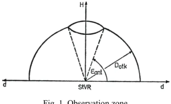
The observation zone is the limited part of the space near the missile guidance station in which – it is possible to detect and to follow air targets.
Fig. 1. Observation zone
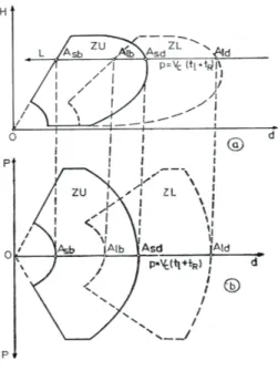
The destroy zone (ZU, Fig. 2) is part of the shooting zone which provides destroying of the target with exact probability. This zone gives the border characteristics of the mis-sile system for destroying of different targets in certain conditions and it represents one of the main characteristics of the combat abilities of the missile system for air defence.
In order to obtain the meeting point between the missile and the target in the destroy zone, the missile must be launched on time, and it must be taken in consideration - the target velocity, its manoeuvring capabilities and flying time of the missile to the meeting (collision) point As ( Asb < As < Asd). Accordingly, the launching zone (ZL, Fig.2) is part
of the space around the launching station in which the missile is situated in the moment of launching; this calculation will provide the meeting point between the missile and the target in the destroy zone (Fig. 2).
Fig. 2. Destroy and launching zones
One can conclude from the above discussion that in the fire control task we have to use different devices for distant detection of the targets, computers that provide selection and direction towards the target, radar and optical sensors for correct locating (coordina-tion’s calculation) of the target, computers for control of the command lines for remote transfer, and operation of other system components. The system for fire control together with the controlled object (the missile) is very complex technical system and all the operators of the system have rigidly defined tasks.
The detection and the recognition of the target, the determining of the target flying pa-rameters, the missile launching and its collision with the target, are a sequence of opera-tions which are integral part of the fire control system and the missile systems for air de-fence.
3. THE NOVEL MODE OF FIRE CONTROL
The device for estimation of the launching zone (AOZ) is applied for calculation of the launching zone borders, and for checking whether the target is inside the launching zone. After reception of the launching command - the necessary passing angles are calcu-lated and transferred to the launching devices (just before launching). The calculation of the launching borders and the passing angles are made on two different analogous com-puters. The calculations and comparison in the past were made in analogous manner by employing analogue computing devices, and all the hardware components were set up only for one algorithm and one missile system (e.g., for instance, Strela-10). Because of this old-fashion and very inflexible manner of computer usage (analogous), we propose modifications in the device for calculation of the launching zone.
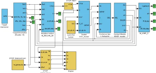
The new method for calculation is performed on the following manner. Firstly - the launching and destroy zones for the concrete missile system are calculated for different flying regimes of the target and different target velocities (Deskovski et al. 2003). These data are stored in computer’s memory together with the passing angles and the flying times to each border point of the destroy zone. For determining the launching and destroy zones - we use simulation model of the system which determines the real zones for all regimes. One such simulation system is given on Figure 3.
The launching zone is chosen using a fuzzy reasoning system to process an equivalent fuzzy variable for the target velocity.
Fig. 3. Simulation model of the homing-guidance system for calculation of launching and destroy zones.
If a target is detected in the air and primary information obtained, the computer calcu-lates the flying parameters of the target. Thereupon the data for the closer, Db, and the
more distant, Dd, border of the destroy zone, as well as flying times to these borders, are
loaded from the storage memory. Based on these data - the closer and the more distant borders of the launching zone are calculated for each border point of the destroy zone. The results of these calculations are DLb (closer) and DLd (more distant) border of the
launching zone.
In the next step, a check is made - whether the distance to the target lays inside the borders of the launching zone, i.e. if this condition is satisfied:
Ld c Lb R D
D 〈 〈
If the condition is satisfied - (for the measured parameters about the target’s flying pa-rameters), the launching angle will be loaded from the computer’s memory and the signal “ZONE” is formed which comes from the operator’s desk; the signals that are propor-tional to the passing angle (after the D/A conversion) are brought to the input of the servo device. They serve for the starting movement of the launching device. Based on the ob-tained results - the data for the launching and annihilation zones are loaded (they were previously stored in the computer memory).
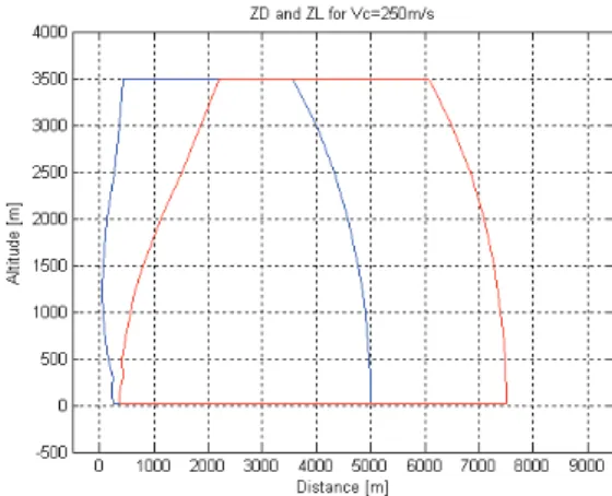
Fig. 4. Computed launching zone and destroy zone Vc = 250 m/s
The zones can be drawn in vertical and horizontal plane (depend on what is required). One such drawing is given on Figure 4.
4. FUZZY RULE KNOWLEDGE BASE FOR THE FIRE CONTROL SYSTEM
The system for fire control uses fuzzy reasoning, i.e. intelligent decision-making (Zadeh, 1983; Berenji, et al. 1991; Klir,et al. 1995; Ross, 2004). In order to perform shoot-ing on target – there must be an alarmshoot-ing system, so called sensory subsystem, which will determine the launching zone, based on the velocity and the height of the target.
The rule base, in linguistic terms, is as follows: IF Vc is very_fast THEN Zona is very_far IF Vc is fast THEN Zona is far
IF Vc is medium THEN Zona is medium IF Vc is slow THEN Zona is close
IF Vc is very_slow THEN Zona is very_close
The real values of the Velocity belongs in the range Vc=[100-400] m/sec, albeit the most tar-get have velocities Vc=[150-350] m/sec. The real values of the variable Launching Zone be-longs in the range Zona=[0-2000] m, i.e. for very fast targets, it is translated up to 2000 metres.
After the signalization that the target enters the launching zone, the intelligent fire control system enables to the operator – launching of the missile in 5 different moments (while the target is in the zone). If the missile is not launched in one of those moments, the target will pass un-destroyed.
After launching of the missile - its trajectory is drawn using the matrix obtained from the Simulink model. The simulation is implemented in Matlab-Simulink, and has three steps: 1) informing when the target enters the launching zone, 2) movement of the target in the zone, until the operator makes decision for launch, 3) missile launching and its movement toward the target.
5.SIMULATION RESULTS
Assume the target is moving directly straight towards the positioned anti-aircraft mis-sile defence system.
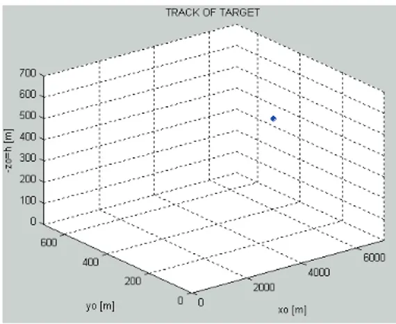
Fig. 6. The target is in motion.
For the given velocity detected, the system drawing “Launching zone and destroy zone” is computed, which are depicted in Figure 7.
When the target enters the launching zone - an announcement is given that the target is inside the launching zone as depicted in Figure 8.
Fig. 8. Information - The target in launching zone.
Than we are asked if we want to execute the launching of the missile. If yet, then 1 is entered, and if not, then 2 should be entered.
Fig. 9. Do you want launching missile?
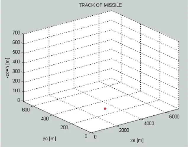
After the launching, we follow via simulation the movements of both the target and the missile as they evolve, and a final result is obtained – the target is either destroyed or it is not destroyed.
Fig. 10. Missile in motion seized to exist.
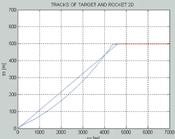
In Figure 12, there are presented 2 trajectories of the missile in the motion to intercept the target. The first line is an ideal trajectory of the missile (kinematics’ trajectory), while the curved line is the real (actual) trajectory of the missile.
Fig. 12. Trajectories of the missile and the target in the vertical plane.
6.CONCLUSION
A novel computer simulation based method that is suitable for early alert and fire con-trol in missile air-defence systems has been developed. Although being a software based technique, it makes efficient usage of all the hardware of missile air-defence systems as appropriate. It relies on the sensor subsystem for early detection, identification and measurement target’s flying parameters in the air. It can improve considerably the control computing for the fire control with regard to both calculations of the collision point and of the shooting parameters. The device for calculation of the launching zone (AOZ) is used for intelligent estimation to establish whether the target has entered the launching zone or not. The model was developed by using Matlab’s Fuzzy toolbox and the Simulink.
The proposed novel approach makes essential use of a fuzzy reasoning to calculate the launching zone immediately upon the first detection of a target, i.e. a fuzzy-rule knowledge base for target’s velocity. Namely, it uses pre-defined launching zones for different flying regimes and different velocities of potential targets, and the data are stored into a look-up table along with the associated pass angles and flying times to the launching zone border. Still, the most important components of the fire control systems are the sensors for early detection, identification, and velocity estimation of enemy airborne weapons.
REFERENCES
1. Berenji, H. R. (1991). Fuzzy logic controllers. In: R. R. Yager and L. A. Zadeh, editors, An Introduction to Fuzzy Logic Applications in Intelligent Systems, Kluwer Academic Publishers. New York, US. 2. Davis, L. Jr., J. W. Follin Jr., and L Blitzer (1958). The Exterior Ballistics of Rockets. D. Van Nostrand
Co., Princenton, NJ – US.
3. Deskovski, S. (2004). Homing Guidance and Missile Systems for Air Defence. MA of ARM, Skopje, MK (in Macedonian).
4. Deskovski, S., Z. Gacovski, and G. Dimirovski (2003). Homing guidance laws using applied fuzzy sys-tems. In: Proceedings of the 1st International Conference on Recent Advances in Space Technologies (RAST03), Istanbul, Nov. 20-22, pp. 673-678. Turkish Air Force Academy, Istanbul, TR.
5. Dimirovski, G. M. (1995). Foundations of Digital Fuzzy-knowledge Based Control, Lecture Notes of IASE. FEE of EE SS Cyril and Methodius University, Skopje MK (in Macedonian).
6. Dimirovski G. M. (2002). “New Trends in Missile Control and Guidance using Fuzzy Systems” (Key-note Lecture). In: First Symposium for Explosive materials, Weapons and Military Technology, Septem-ber 25-28, Ohrid, Rep. of Macedonia. MA-ARM, Skopje, MK.
7. Dimirovski, G., S. Deskovski, and Z. Gacovski (2004). Classical and fuzzy-system guidance laws in homing missile systems. In: Proceedings of the 2004 IEEE AESS International Aerospace Conference, March 6-13, Big Sky, Montana , pp. 9.0204.(1-18). The IEEE, Piscataway, NJ, and IEEE Aerospace Conferences Office, Manhattan Beach, CA, USA.
8. Gelev, S., S. Deskovski, and Z. Gacovski (2003). Simulation model for determining the launching zones for missile systems for air defence. In: Proceedings of the 6th National Conference ETAI 2003 with International participation, Ohrid, pp. A63-A68. Society for ETAI, Skopje, MK.
9. Gelev, S., S. Deskovski, and Z. Gacovski (2005). Simulation model for early warning for air defence missile. In: Proceedings of the 7th National Conference ETAI 2005 with International participation, Ohrid, pp. A117-A122. Society for ETAI, Skopje, MK.
10. Klir, G. J., and Bo Yuan (1995). Fuzzy Sets and Fuzzy Logic–Theory and Applications. Prentice Hall PTR, Upper Saddle River, NJ.
11. Knezevic, S. (1980). Theory of Guided Ground-to-air Missiles. Military Publishing Co., Belgrade, SR (in Serbo-Croat).
12. Malygin, A. S. (1978). Fire Control of Missile Systems for Anti-aircraft Combat. Voennoe Izdatelstvo MO SSSR, Moskva, RU (in Russian).
13. Mohenski, D, G. Dimirovski G., and S. Deskovski (2000). Fuzzy rule-based system for determining the launching zones for light anti-aircraft missiles. In: Proceedings of the 5th National Conference ETAI 2000 with International Participation, Ohrid, MK, pp. A-94-A99. Society for ETAI, Skopje, MK.
14. Neupokoev. F. K. (1970). Shooting by Zenith Rockets Voennoe Izdatelstvo MO SSSR, Moskva, RU (in Russian).
15. Peresada. S. A. (1973). Horizon Zenith Rocket Complexes. Voennoe Izdatelstvo MO SSSR, Moskva, RU(in Russian).
16. Ross, T. J. (2004). Fuzzy Logic with Engineering Applications. J. Wiley & Sons, Ltd., Chichester, England, UK. 17. Siouris, G. M. (2004). Missile Guidance and Control Systems. Springer-Verlag, New York, US. 18. Xu, L.-H., Y.-W. Jing, G. M. Dimirovski, and L.-D. Shi (2006). On UKF Based Filter in INS/GPSS
Inte-grated Navigation Systems: Pt I Theory; Pt II Applications (Joint Research Report). ICS-SIS&T of Northeastern University, Shenyang, P.R. of China, and DCE-FE of Dogus University, Istanbul, TR. 19. Yen, J., and R. Langari (1998). Fuzzy Logic: Intelligence, Control, and Information. Prentice Hall, Upper
Saddle River, NJ – US.
20. Zadeh, L. A. (1983). The role of fuzzy logic in the management of uncertainty in expert systems. Fuzzy Sets and Systems, vol. 11, pp 199-221 (Elsevier Science Publishers BM North-Holland).
SAMONAVOĐENJE VAZDUŠNIH RAKETNIH SISTEMA POMOĆU
NOVOG FAZI-LOGIČKOG MODUSA UPRAVLJANJA PALJBE
Saso Gelev, Zoran Gacovski, Stojce Deskovski, Georgi M. Dimirovski
Problem pogađanja ciljeva u vazduhu je prilično kompleksan zadatak u kome je svaki raketni system za odbranu iz vazduha odgovoran za upravljanje paljbe. U ovom radu predstavljamo novi pristup i modus za upravljanje paljbe u sistemima odbrane protiv-vazdušne zasnovane na samonavođenjim raketama. Sredstvo za izračunavanje lansirne zone (AOZ) koristi se za tačnu procenu da li je cilj ušao u lansirnu zonu. Predloženi novi pristup u suštini koristi fazi logiku, baza znanja fazi-principima za brzinu cilja, da bi se procenila lansirna zona odmah po prvoj detekciji cilja. Naime, ona koristi pre-definisanu lansirnu zonu za različite režime letenja i različite brzine potencijalnih ciljeva, i podaci se čuvaju u tabeli traženja sa odgovarajućim prolaznim uglovima i vremenima letenja do granice lansirne zone. Komputerski modeli simulacije i eksperimenti simulacije realizuju se uz pomoć novog modela koji je napravljen u Matlab-Simulink platformi.
Ključne reči: Vazdušna odbrana, rano upozorenje, upravljanje paljbe, samonavođenje, procena lansirne zone, raketni siystem, simulacioni model